Lever roll-up shade with stop damper

a technology of lever and roller, which is applied in the direction of monocoque construction, suspension device, building components, etc., can solve the problems of hard impact when the pull rod or the lever strikes the housing accordingly

Inactive Publication Date: 2012-05-01
BOS
View PDF18 Cites 3 Cited by
  • Summary
  • Abstract
  • Description
  • Claims
  • Application Information

AI Technical Summary

Benefits of technology

[0009]It is an object of the invention to provide a lever actuated roll-up shade for motor vehicles in which noises associated with the shade reaching a retracted end position are greatly reduced.
[0012]A stop brake device is located in the vicinity of the wind-up shaft in the movement path of the pivot-lever arrangements. The stop brake device is constructed so that it slows the movement of the pivot-lever arrangements upon movement into the rest position, which corresponds to the retracted state of the roll-up shade. In this way, hard impact noises are prevented when the pull rod reaches the limit at the end of its retracted movement.
[0013]Here, the stop brake device can also be used as a mechanical stop that defines the end position. In particular, for lever actuated roll-up shades practically no tolerance problems occur because the lever extends almost exactly horizontal in the retracted position so that maladjustments of the stop brake device lead to no positional error.
[0017]A good braking effect can be achieved when the elastomer part has two semi-cylindrical walls coaxial to each other as the stop brake device. The semi-cylindrical walls can be connected to each other by bracing walls that extend approximately in a radial direction. In such case, the outer wall in the radial direction can also be supported on the inner wall in the radial direction when the outer wall is deformed.
[0018]The stop brake device can consist of two elements that move relative to each other and that are pretensioned by means of a spring into a starting position. The elements may project one inside the other in a telescoping way, and the pretensioning device can be formed by a helical spring which reduces the space requirements. A frustum-shaped brake element, which has a through-hole through which one of the two moving elements is guided, can be used between the elements moving relative to each other. Favorable driving relationships are produced when the pretensioning device is coupled to the wind-up shaft. The pretensioning device can be formed by a spring motor.

Problems solved by technology

For support, two holding grooves, in which the pull rod travels, is located at the top end of the rear window so that vibrations in connection with the elasticity of the two-armed levers do not permit the pull rod to contact the window.
The impact when the pull rod or the levers strike the housing accordingly can be hard.

Method used


Image

  • Lever roll-up shade with stop damper
  • Lever roll-up shade with stop damper
  • Lever roll-up shade with stop damper

Examples


Embodiment Construction

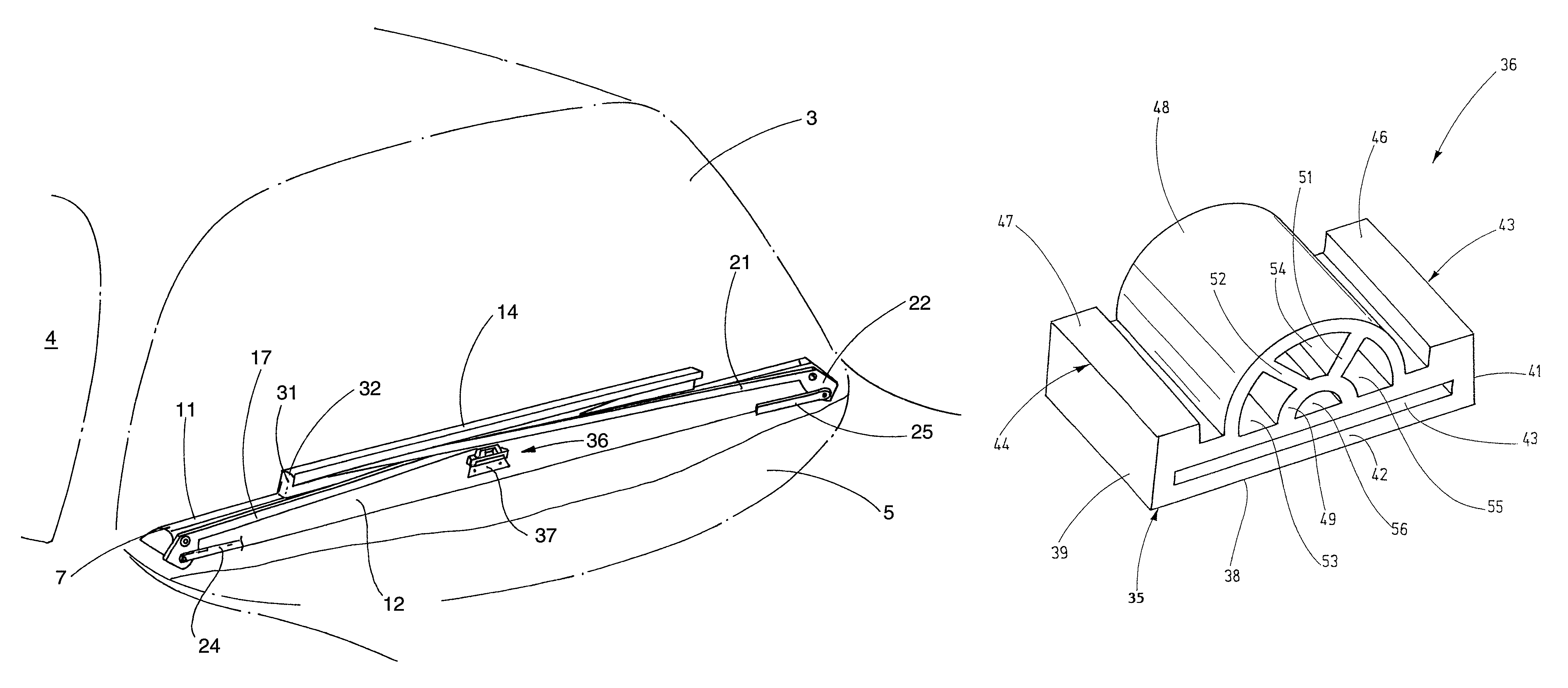
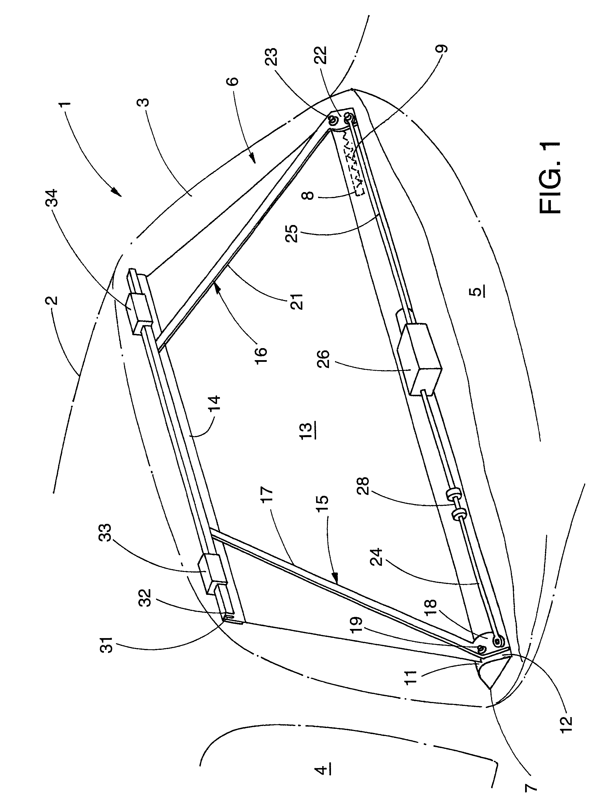
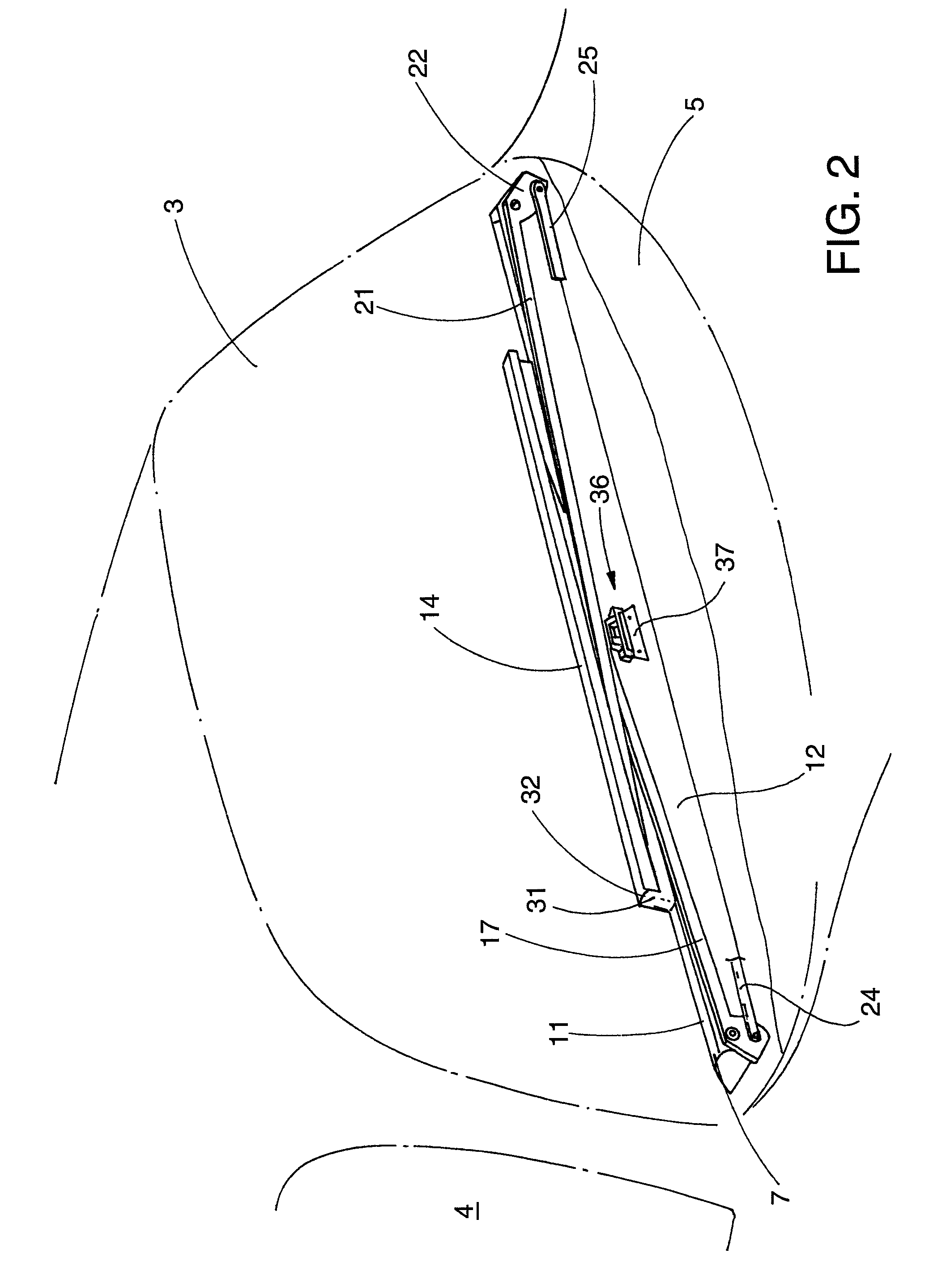
[0029]Referring now more particularly to FIG. 1 of the drawings, there is shown an illustrated motor vehicle having a roll-up shade assembly 6 in accordance with the invention. As depicted from the rear in FIG. 1, the vehicle has a stepped back with a roof 2 that joins a rear window 3. The vehicle further has back side window panes 4, the left side pane of which is depicted in FIG. 1. In the interior of the vehicle in front of the rear pane 3, there is a rear seat shelf 5 which extends in a known manner to the rear side of a rear seat backrest. A rear window roll-up shade assembly 6 is disposed within the passenger compartment next to the rear pane 3.

[0030]The illustrated roll-up shade assembly 6 includes a roll-up shade housing 7 which can be arranged on or underneath the backseat shelf 5. Within the housing 7, which extends across the entire width of the back seat shelf 5 or the bottom edge of the rear pane 3, a wind-up shaft 8, depicted in dashed lines, is notably mounted. A spri...


PUM


Abstract

A lever actuated roll-up shade assembly for motor vehicle windows having a stop brake for slowing down movement of actuating levers of the roll-up shade assembly during movement into a position corresponding to the retracted position of the roller shade so as to prevent loud impact noises.

Description

CROSS-REFERENCE TO RELATED APPLICATIONS[0001]This patent application claims the benefit of German Patent Application No. 102007032435.0-56, filed Jul. 10, 2007, which is incorporated by reference.FIELD OF THE INVENTION[0002]The present invention relates generally to roll-up shade assemblies, and more particularly, to roll-up shade assemblies for the rear windows of motor vehicles.BACKGROUND OF THE INVENTION[0003]EP 0 240 747 A1 describes a lever actuated roll-up shade for motor vehicles. The roll-up shade is to be used for reducing solar radiation through the rear window in order to prevent the interior from heating up quickly. In addition, the extended roll-up shade reduces the demands on the air-conditioner when there is strong solar radiation.[0004]The known roll-up shade has a wind-up shaft mounted so that it can rotate in a roll-up shade housing. Two two-armed levers spaced apart along the wind-up shaft are hinged to the housing. The rotational axis of the levers lies perpendic...

Claims


Application Information

Patent Timeline
Patent Type & Authority Patents(United States)
IPC IPC(8): B60J3/00
CPCB60J1/2019B60J1/208B60J1/2055B60J3/00B60J3/02
Inventor LEKAR, JAN
Owner BOS
Why Eureka
Try Eureka