Power plug with a freely rotatable delivery point

a technology of power plugs and delivery points, which is applied in the direction of flexible/turnable line connectors, electrical discharge lamps, coupling device connections, etc., can solve the problems of direct affecting the efficiency of transmitting electric current, difficult wiring, and large mechanical stress, and achieve the effect of absorbing mechanical vibration waves

Active Publication Date: 2012-05-01
MIG SURGE TECH
View PDF5 Cites 796 Cited by
  • Summary
  • Abstract
  • Description
  • Claims
  • Application Information

AI Technical Summary

Benefits of technology

[0007]The primary object of the present invention is to provide a power plug with a freely rotatable delivery point, wherein a plug seat of the present invention includes a planar armature which can displace forward and backward along an axial direction, the armature corresponds coaxially to a turntable to provide assembling with terminals, an end of each terminal is provided with a conducting slip ring which contacts with and conducts the armature respectively and an elastic arch element is provided between an interior of the seat and the armature to effectively absorb a mechanical vibration wave when the terminals rotate relatively to the armature, assuring that the terminals can actually contact with the armature, thereby forming a smooth path through which the electric current can flow easily and providing a smooth mechanical operation.
[0008]Another object of the present invention is to provide a power plug with a freely rotatable delivery point, wherein an end of insertion terminal toward a contact point with the armature is extended with a conducting probe with an elastic shear, which can absorb a mechanical gap jump produced when the terminal moves relatively to the armature, allowing the elements to be clearly in touch with one another and facilitating the electric current to flow through a smooth path.

Problems solved by technology

In particular, for an electric appliance with a larger demand of electric current, an electric wire carried by the power plug is coarser, which results in a larger mechanical stress, such that it will be difficult to carry out insertion and wiring or even that a plate-typed insertion terminal needs to be bended.
However, for conducting electricity, whether contact between conducting elements is tight and solid or not will directly affect an efficiency of transmitting the electric current.
If the contact is inherently imperfect or a jump occurs when a gap is caused by a vibration wave which is produced when the orientation is changing, then resistors will generate heat or jump sparks will be formed, causing an unnecessary loss.

Method used


Image

  • Power plug with a freely rotatable delivery point
  • Power plug with a freely rotatable delivery point
  • Power plug with a freely rotatable delivery point

Examples


Embodiment Construction

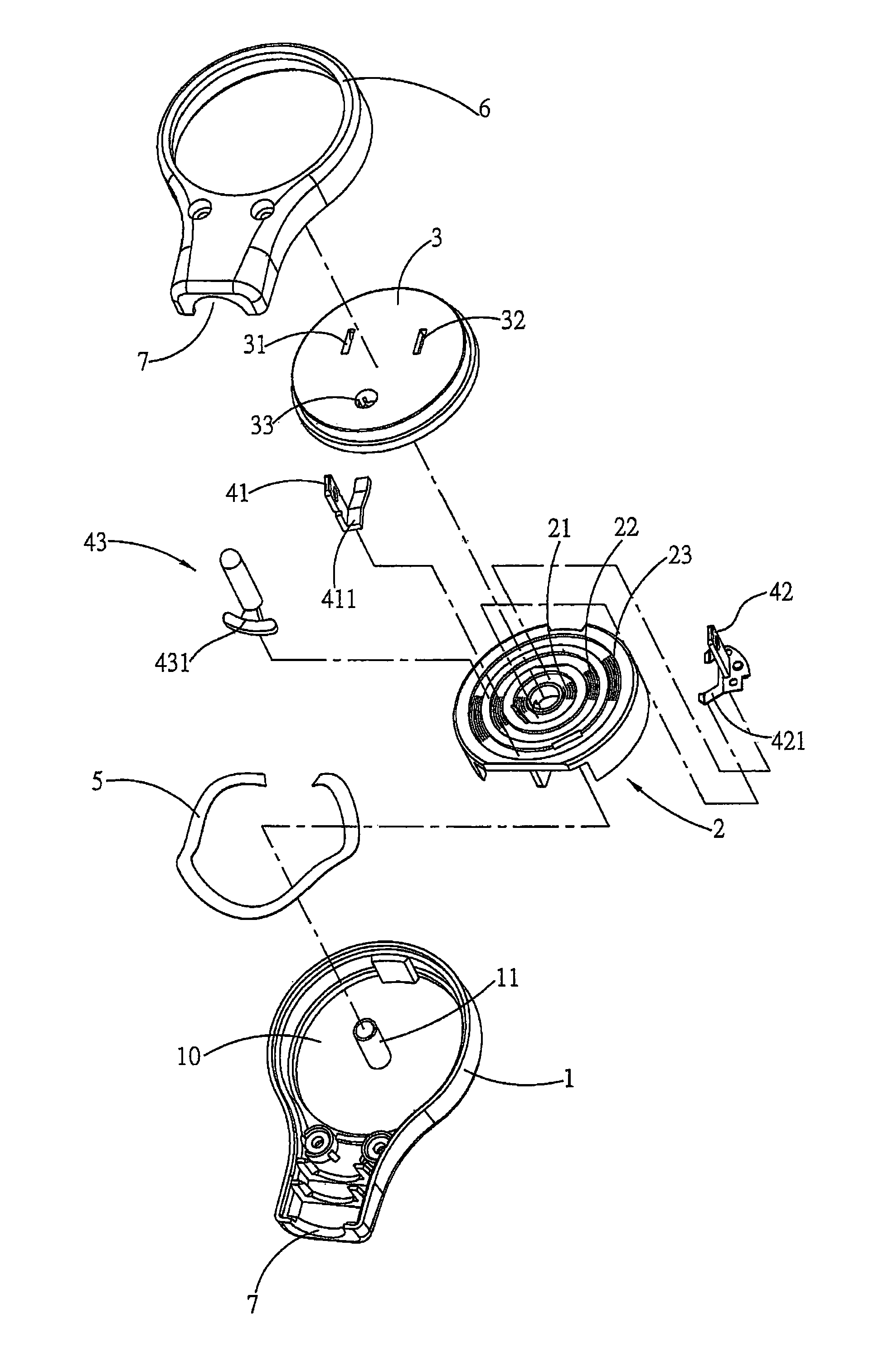
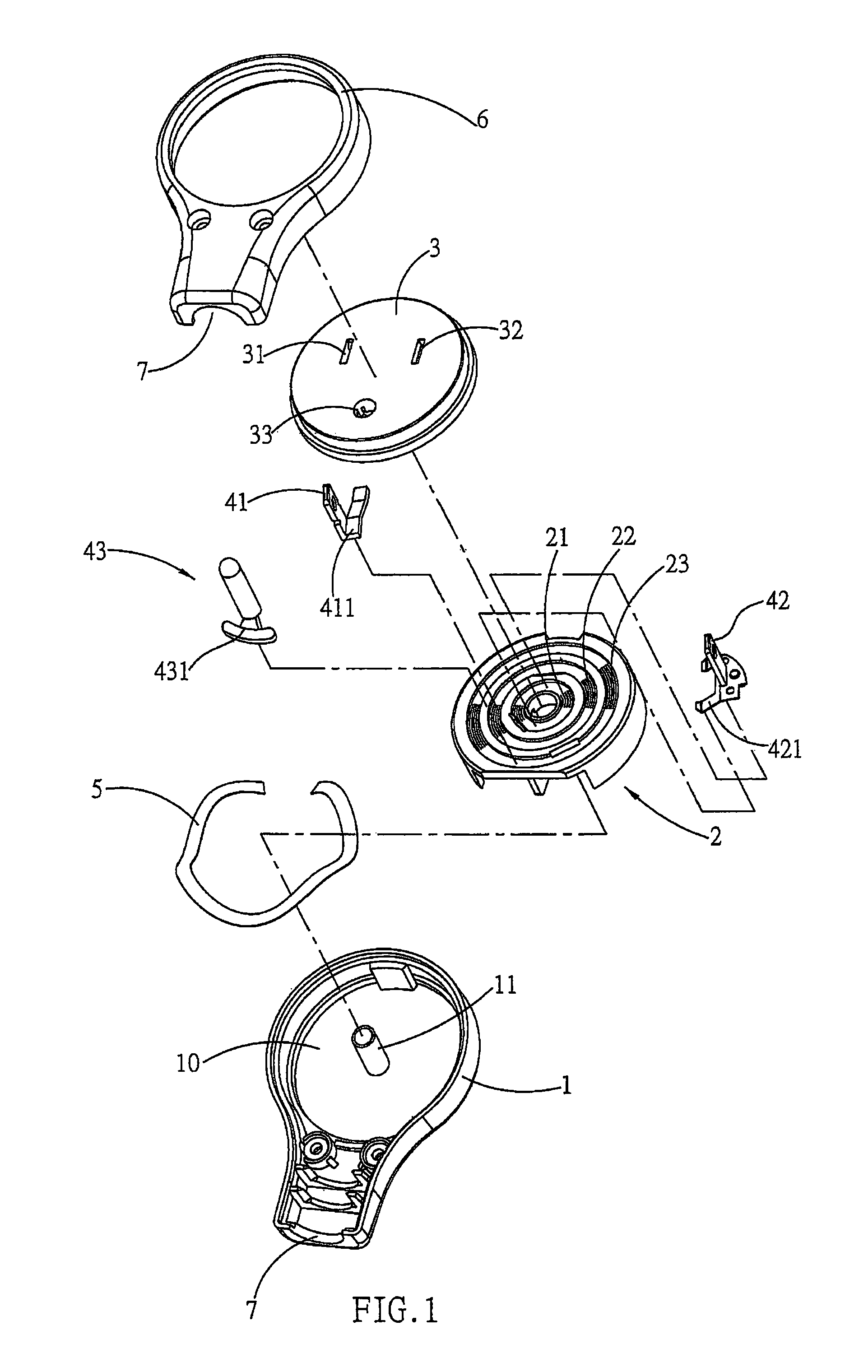
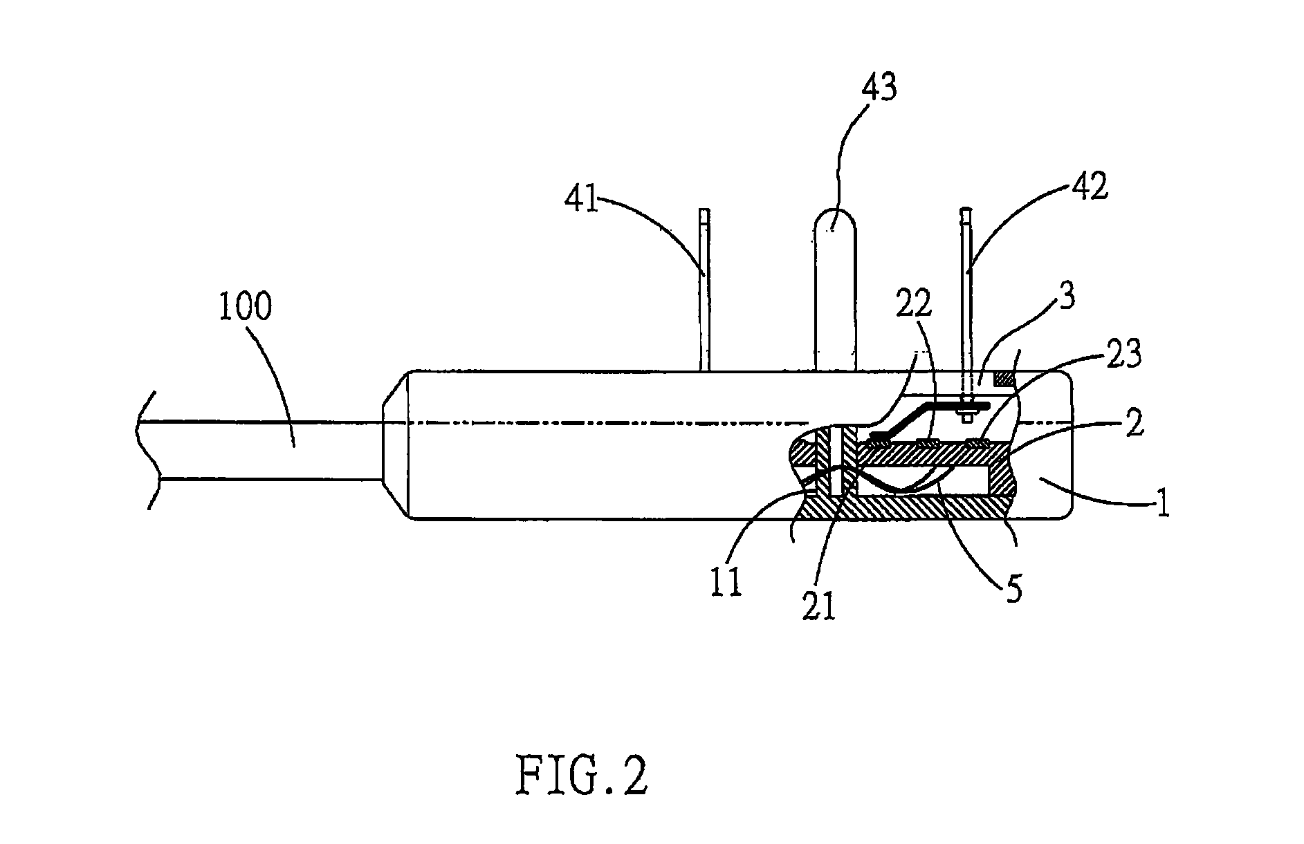
[0012]A power plug with a freely rotatable delivery point includes insertion terminals of the plug, wherein a relative orientation between an electric conducting element (electric wire) carried by the plug and the plug can change freely. Basically, the plug which is referred to in the present invention is an F-typed plug, wherein the provided insertion terminals are located at an end surface relative to a plug seat to rotate by any angle on a plane, removing a vibration wave between the elements during movement, such that electricity can be actually conducted, sparks can be avoided and a mechanical operation can be successful.

[0013]The present invention comprises primarily a seat, an interior of which is formed with an indented space to install a planar armature that can displace axially. A center of the armature aligns exactly with a center axis of the seat and is coaxially overlapped. A working plane of the armature is distributed with plural conjugated conducting slip rings of un...


PUM


Abstract

A power plug with a freely rotatable delivery point is disclosed, wherein a relative orientation between a delivery point element (e.g. an electric wire) and insertion terminals of the plug can change freely on a plane. A plug seat includes an armature which displaces axially. An open end of the seat is loosely connected with a turntable which is coaxial with the armature. The turntable is assembled with the insertion terminals which loosely contact with the armature by relative rotation. Between the seat and the armature, an elastic arch element is axially provided and parts of the insertion terminals relative to the armature are indirectly provided with plate-shaped conducting probes with an elastic shear. By the elastic arch element and the conducting probes, a mechanical vibration wave occurring during rotation of the turntable is absorbed, such that the armature can actually contact with the terminals to avoid jump sparks.

Description

BACKGROUND OF THE INVENTION[0001]a) Field of the Invention[0002]The present invention relates to a power plug with a freely rotatable delivery point and more particularly to a power plug, wherein a relative angle between insertion terminals and a seat can rotate freely to avoid jump sparks and facilitate operation when rotating the insertion terminals. The power plug includes primarily a plug seat, an interior of which is assembled with an armature and a turntable that is coaxial with the armature. The turntable provides for installation of the insertion terminals, an opposite longitudinal surface between the armature and the seat is indirectly provided with an elastic arch element and plate-typed conducting probes with an elastic shear are indirectly provided between the insertion terminals and the armature. By an elastic stress action between the elastic arch element and the conducting probes, a mechanical vibration wave of motion can be absorbed to avoid gap jump.[0003]b) Descrip...

Claims


Application Information

Patent Timeline
Patent Type & Authority Patents(United States)
IPC IPC(8): H01R39/00
CPCH01R24/30H01R35/00H01R2103/00
Inventor ZHOU, JIAN-LIN
Owner MIG SURGE TECH
Why Eureka
Try Eureka