Endoscope light source unit

a technology of light source unit and endoscope, which is applied in the field of endoscope light source unit, can solve the problem that the controller does not allow the rotary aperture pla

Inactive Publication Date: 2012-05-01
HOYA CORP
View PDF12 Cites 62 Cited by
  • Summary
  • Abstract
  • Description
  • Claims
  • Application Information

AI Technical Summary

Benefits of technology

[0028]According to the present invention, the rotary aperture plate can be prevented from being at a full-aperture state in the case of a malfunction in an endoscope light source unit which incorporates a rotary aperture device that changes the opening ratio by changing the rotation position of the rotary aperture plate.
[0029]Even if the endoscope light source unit is provided with an auxiliary light source and can select an opening having a maximum opening ratio for the auxiliary light source, this opening can be prevented from being accidentally inserted into an optical path of the light source unit during normal use.

Problems solved by technology

When the auxiliary light is in the retracted position, the controller does not allow the rotary aperture plate to stop at a position where the second sensor detects the first sensing portion.

Method used


Image

  • Endoscope light source unit
  • Endoscope light source unit
  • Endoscope light source unit

Examples


first embodiment

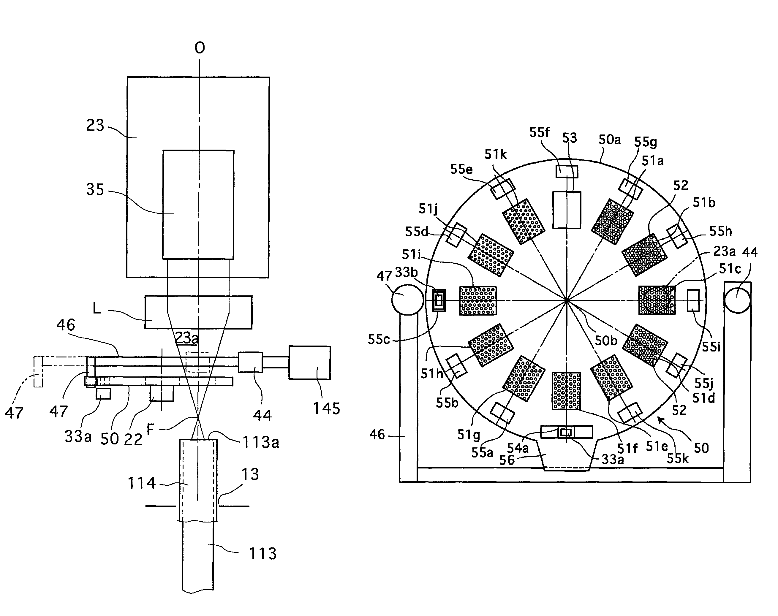
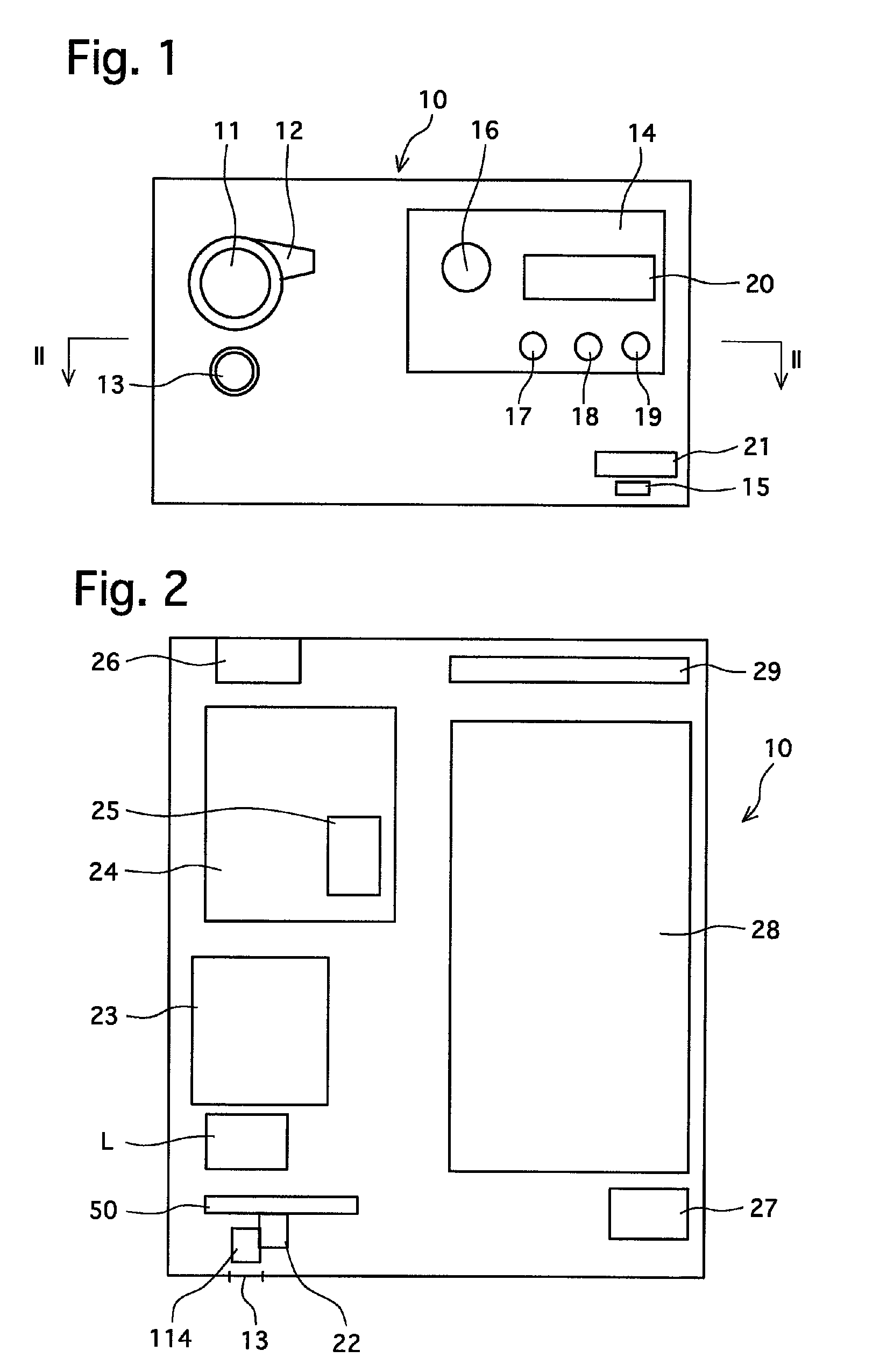
[0049]FIG. 1 is a front elevational view of an embodiment (first embodiment) of a processor 10 that serves as an endoscope light source unit according to the present invention. FIG. 2 is an abbreviated cross sectional view taken along the II-II line shown in FIG. 1, showing main components of the processor 10.

[0050]The processor 10 is provided on the front thereof (as viewed in FIG. 1) with a scope socket 11 into which a connector 104 of an electronic scope (electronic endoscope) 100 is to be inserted (see FIG. 4), and a scope lock lever 12 for locking the inserted connector 104 so as not to come out. The scope socket 11 establishes connection with connect pins, or the like, provided in the connector 104 of the electronic scope 100. A light guide socket 13 for a light guide connector of the electronic scope 100 (or a fiber scope) is formed below the scope socket 11.

[0051]The processor 10 also has an operation panel 14 on the front thereof, beside the scope socket 11 (on the right si...

second embodiment

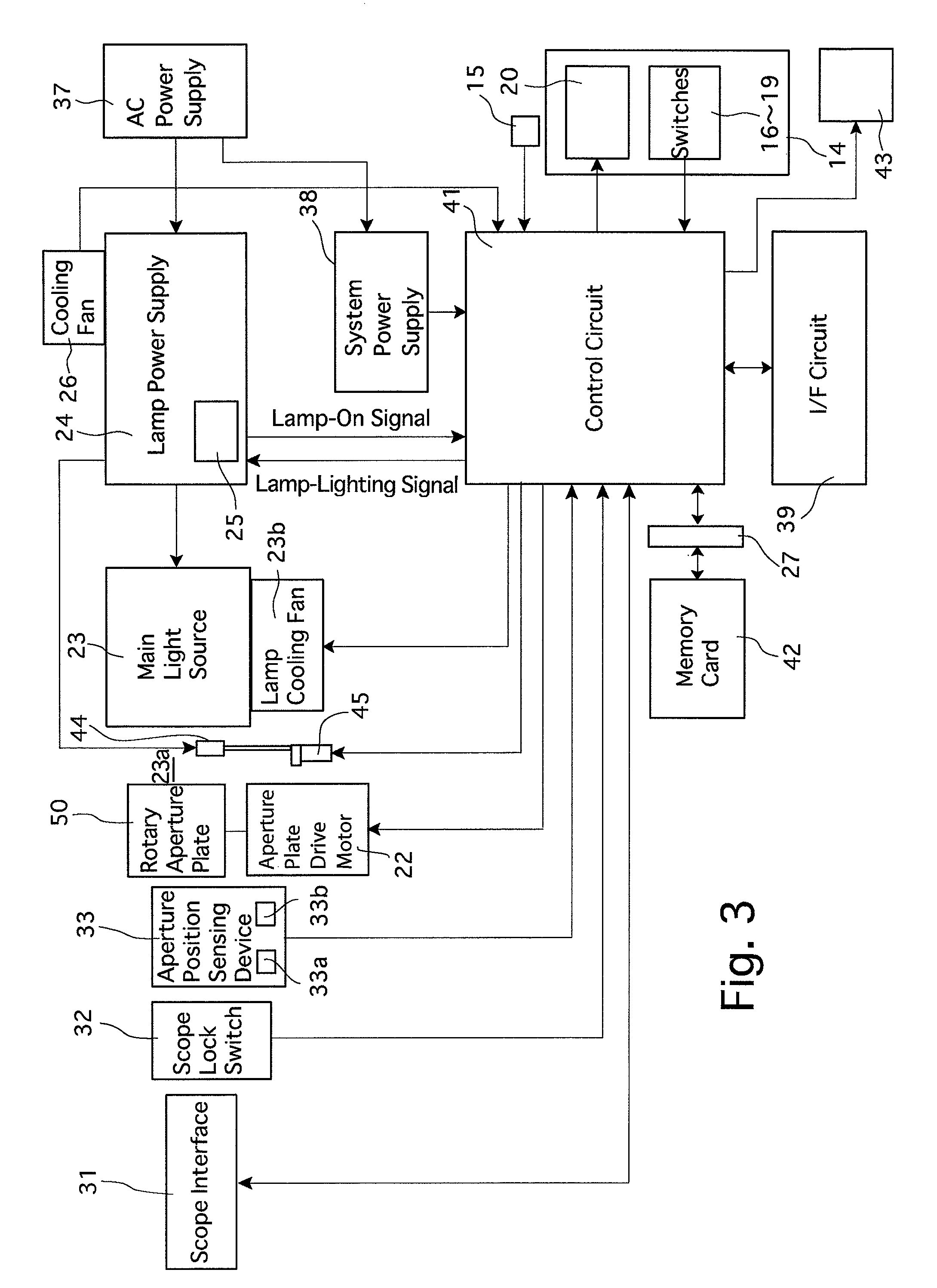
[0104]In the processor, the rotary aperture plate 50 is further provided with a projection (rotation control device) 56 which projects radially outwards in a radial direction away from the sixth aperture opening 51f to prevent the rotary aperture plate 50 from stopping at the position of rotation thereof at which the auxiliary-light aperture opening 53 is positioned in the light-source optical path 23a in normal use.

[0105]The processor 10 has an auxiliary light (auxiliary light source) 44 (see FIG. 13) that comes into operation when the lamp 35 of the main light source 23 accidentally goes out due to some reason. The auxiliary light 44 is fixed to one end of a substantially U-shaped movable frame (linkage member) 46 that is positioned between the rotary aperture plate 50 and the main light source 23 so as to extend around the light-source optical path 23a. A safety-member driving solenoid (electromagnetic solenoid / driving device) 145 is connected to the movable frame 46 (see FIG. 13...


PUM


Abstract

An endoscope light source unit for making illumination light incident on a light guide, includes a rotary aperture plate, aperture openings of different opening ratios and an auxiliary-light aperture opening of a maximum opening ratio formed in the rotary aperture plate; a rotating device; an auxiliary light; a first sensing portion and a plurality of second sensing portions formed in the rotary aperture plate in association with the auxiliary-light aperture opening and the aperture openings; a first sensor which detects the first sensing portion; a second sensor which detects the first sensing portion and detects the second sensing portions; and a controller which controls the rotary aperture plate in accordance with the first and / or second sensors. When the auxiliary light is in the retracted position, the controller drives the rotary aperture plate while the second sensor detects the first sensing portion.

Description

BACKGROUND OF THE INVENTION[0001]1. Field of the Invention[0002]The present invention relates to an endoscope light source unit suitable for an endoscope and / or an electronic endoscope, etc.[0003]2. Description of the Related Art[0004]Recent electronic endoscope systems have been provided therein with a processor having a built-in light source unit for lighting, to which an electronic scope, having an electronic camera mounted on the distal end thereof, or a fiber scope for conducting observation only through optical members, is connected for use. In particular, electronic scopes, with a wide variety of thicknesses and functions suited to different locations of observation, have been provided for use. Processors connectable with various types of electronic scopes and fiber scopes must also have light source units that are compatible with such various electronic scopes and fiber scopes. For this reason, conventional light source units have been constructed to be capable of supplying ...

Claims


Application Information

Patent Timeline
Patent Type & Authority Patents(United States)
IPC IPC(8): A61B1/06
CPCA61B1/0669
Inventor NEGISHI, KIYOSHI
Owner HOYA CORP
Why Eureka
Try Eureka