
Fibre-reinforced joint

a technology of reinforced joints and fibres, applied in the direction of paper/cardboard containers, brushes, weaving, etc., to achieve the effect of easy torn off laminates, easy to be laid, and easy to pin

Active Publication Date: 2012-05-01
LM GLASSFIBER
View PDF17 Cites 17 Cited by
  • Summary
  • Abstract
  • Description
  • Claims
  • Application Information

AI Technical Summary

Benefits of technology

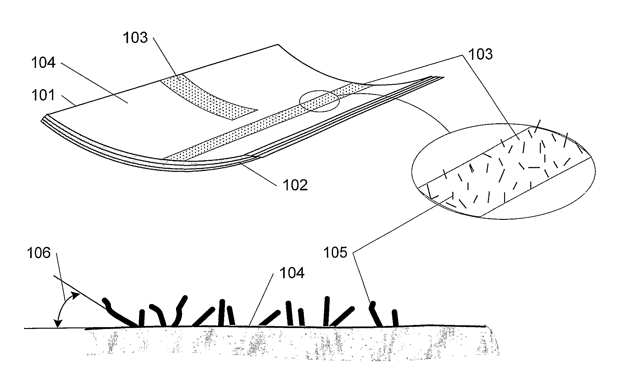
[0008]When the outermost layer has been removed the remaining layers remain on the surface of the laminate with the fibres projecting from the remaining layers and secured thereon. The fibres, which are thus caused to project from the laminate surface, increase the surface area considerably, whereby the adhesion between the laminate and the object(s) to be joined, eg by gluing, is enhanced. Moreover, the fibres act as a fibre-reinforcement of the joint as such, thereby considerably increasing its strength. A further advantage of this method according to the invention is that a subsequent treatment, chemical as well as mechanical, of the areas to be joined is unnecessary. Hereby the discomforts of dust from the conventional grinding process as described in the introductory part are thus avoided; and likewise it is avoided to have to use particular chemicals for cleaning or other treatment of the surface. The prior art techniques referred to in the introductory part for increasing the surface area and hence for improving the adhesion also share the feature that an amount of material is removed from the surface with ensuing damage to same. Opposed to this, the method according to the invention is advantageous in that the ready-moulded surface of the laminate is not damaged, and it is hence ensured that a uniform quality results between the areas for joining and the remainder of the laminate.
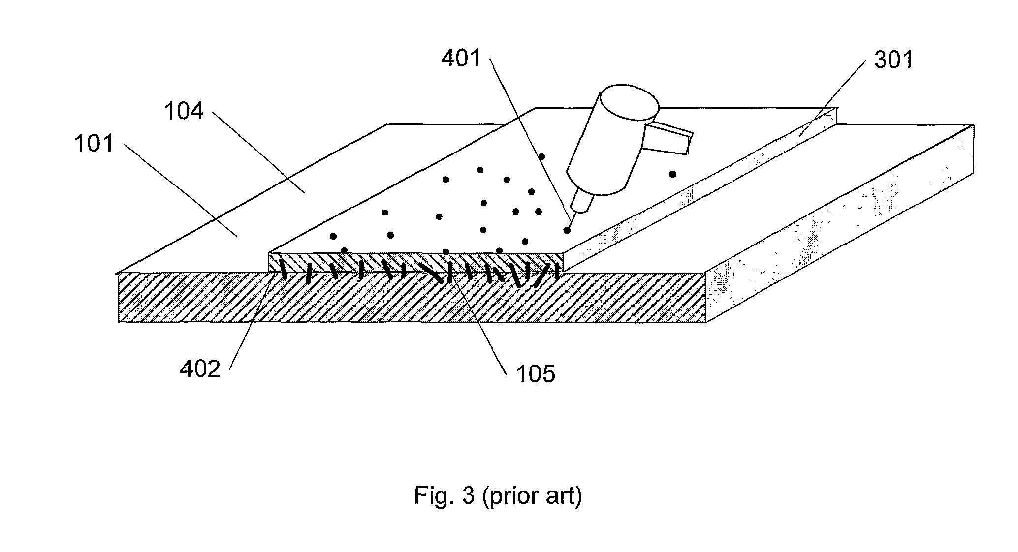
[0019]The invention moreover relates to a method of manufacturing a laminate according to the above comprising arrangement of at least one film between two layers in the hybrid mat. This is advantageous since the film, which may eg be a vacuum cloth or a peel ply, can facilitate tearing off of the outermost layer(s) of the hybrid mat in such a manner that the fibres remain on the surface and project there from. A film can thus prevent that one unintentionally tears off the entire hybrid mat or that one is unable to tear off the entire outermost layer. Finally a film can ensure that the resin penetrates into the outermost layer of the hybrid mat only in a limited amount via the fibres that sit transversally of the joining face and perforate the film. Thereby the outermost layer is more easily pulled off.

Problems solved by technology

The prior art techniques referred to in the introductory part for increasing the surface area and hence for improving the adhesion also share the feature that an amount of material is removed from the surface with ensuing damage to same.

Method used


Image

  • Fibre-reinforced joint
  • Fibre-reinforced joint
  • Fibre-reinforced joint

Examples


Embodiment Construction

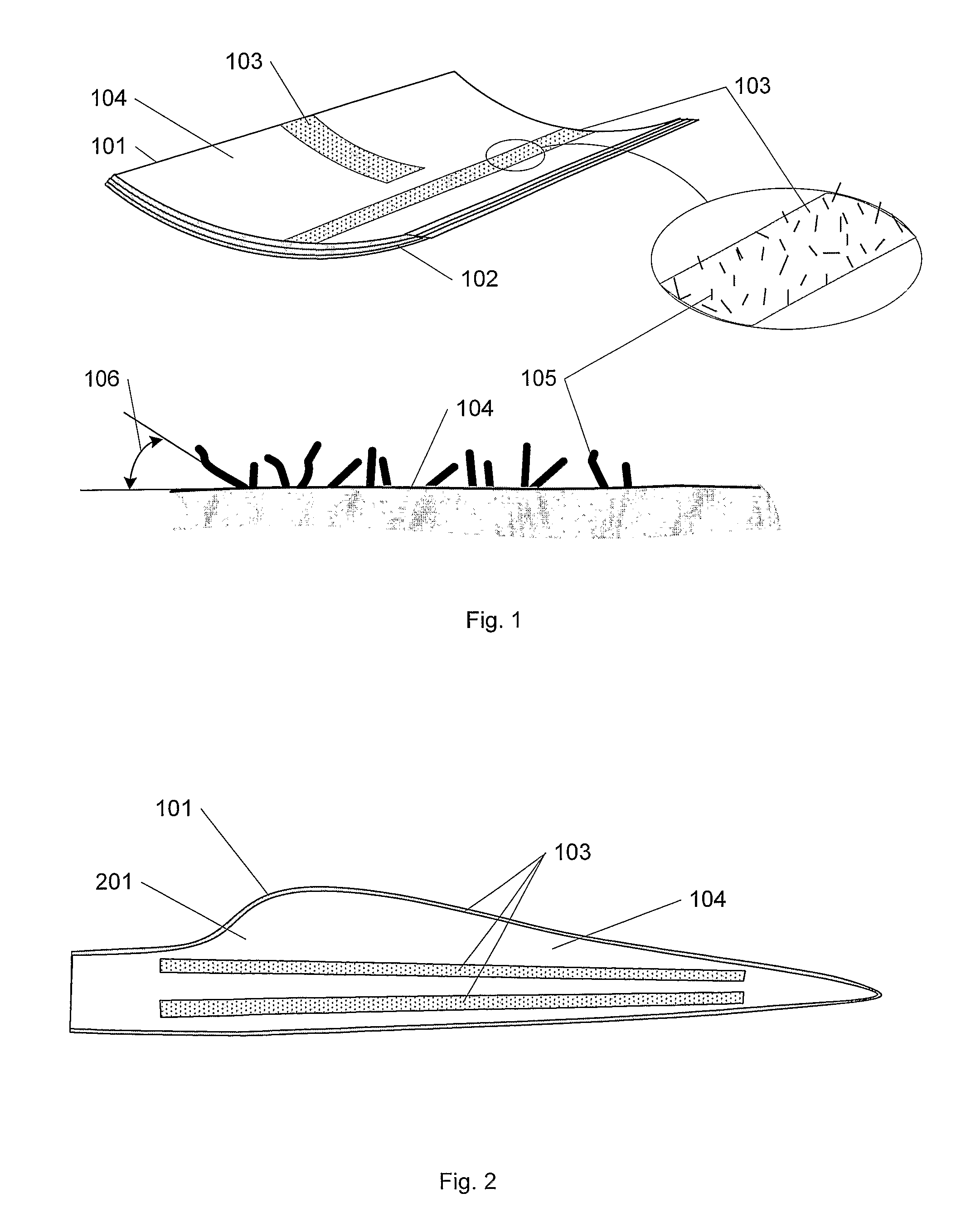
[0034]FIG. 1 shows a laminate 101 structured from a number of layers or laminas 102, of which some or all are reinforced by fibres. The kind of fibre-reinforcement is of no actual consequence to the invention and may be configured in many different ways, eg with long uniformly oriented fibres with woven mats, small short fibres in random arrangement, etc. In the shown areas 103 on the surface 104, the laminate 101 is to be joined to other (not shown) elements, and to improve the strength of the joints, they are reinforced by letting fibres 105 be securely fitted and project from the surface 104. Such joints can be accomplished eg by gluing or by laying a dry or semi-impregnated element on top of an area 103, following which the element is covered by a vacuum cloth and finishing injections are performed locally onto the laminate 101. Some of the laminate surface 104 is shown in an enlarged sectional view in the figure. Moreover, a random section through the laminate 101 is shown, whi...


PUM

PropertyMeasurementUnit
surface areaaaaaaaaaaa
areaaaaaaaaaaa
strengthaaaaaaaaaa

Abstract

The present invention relates to a method of manufacturing a fiber-reinforced laminate (101), which laminate comprises at least one area on the surface of the laminate configured with projecting fibers for being joined to one or more other elements. This is accomplished by arrangement of a hybrid mat (505) most distally in the laminate which comprises at least two layers with fibers (105) transversally across the joining face (402) of the layers. The outermost layer (301) of the hybrid mat is removed prior to joining, whereas the innermost layer (506) of the hybrid mat remains a constituent of the laminate (101). The invention relates to different methods of causing fibers to project from the surface of the laminate, said fibers thus having a reinforcing effect on the joints. The invention also relates to a laminate manufactured by the disclosed methods and a blade for a wind power plant comprising such laminate.

Description

[0001]The present invention relates to a fibre-reinforced laminate and a method of manufacturing a laminate, said laminate comprising at least one area on the surface of the laminate configured for being interconnected with one or more other bodies. The invention also relates to a blade for a wind power plant comprising such laminate.BACKGROUND[0002]When several parts are assembled it is often the strength of the joint as such which is decisive to the strength of the finished element. In the context of fibre-reinforced laminates purely mechanical joints such as bolting, riveting, etc., are most often not particularly suitable. Instead gluing is most often applied or, if two fibre-reinforced elements are concerned, optionally joining by impregnation of the one element onto the other. In order to achieve a joint with sufficient strength, it is usually necessary to treat the surface of the areas on the one or both of the elements to be joined with a view to achieving larger surface are...

Claims


Application Information

Patent Timeline
Patent Type & Authority Patents(United States)
IPC IPC(8): B32B5/12B32B38/10B29C65/00B29C65/56
CPCB29C37/0082B29C70/24B29C70/443B29C70/54Y10T428/24124B29L2031/085Y10T156/10Y10T428/23914Y10T428/24994Y02P70/50
Inventor JACOBSEN, TORBEN KROGSDALOLESEN, MORTEN
Owner LM GLASSFIBER
Learn More