
Electro-dynamic transducer with a slim form factor

a transducer and slim technology, applied in the direction of transducer details, electrical transducers, electrical apparatus, etc., can solve the problems of low resonance frequency, flat speaker design, and small distance between suspension points, and achieve satisfactory stability and low resonance frequency

Active Publication Date: 2012-05-01
BANG & OLUFSEN ICEPOWER GI
View PDF6 Cites 4 Cited by
  • Summary
  • Abstract
  • Description
  • Claims
  • Application Information

AI Technical Summary

Benefits of technology

"The present invention provides an improved electro dynamic transducer with better stability and a lower resonance frequency. The new design allows for a slimmer and more stable system, while also increasing the voice coil diameter without adding extra support structures. The coil former acts as a heat sink, improving the thermal capability of the system. The ratio of maximum-diaphragm-displacement to total-height is approximately one third or higher. The invention can be used in various consumer appliances like automotive audio systems, portable audio / video equipment, home audio systems, PC's, Laptops, and alike."

Problems solved by technology

Fort his reason, conventional speakers have the disadvantage that they are thick compared to their actual diaphragm displacement.
This is of course undesirable for applications like Flat Panel Televisions or placement in a door of a car.
On the other hand, a flat speaker design, with a small distance between the suspension points, will be less stable.
This will have negative audible effects and it can even damage the system during operation.
In a conventional loudspeaker, where the spider is mounted to the peripheri of the coil former, this will result in a reduced effective spider area.
Furthermore it becomes non linear already for small displacements.
However, a drawback with the system in U.S. Pat. No. 6,819,773 is that it requires a specific shape of the diaphragm, restricting the design freedom.

Method used


Image

  • Electro-dynamic transducer with a slim form factor
  • Electro-dynamic transducer with a slim form factor
  • Electro-dynamic transducer with a slim form factor

Examples


Embodiment Construction

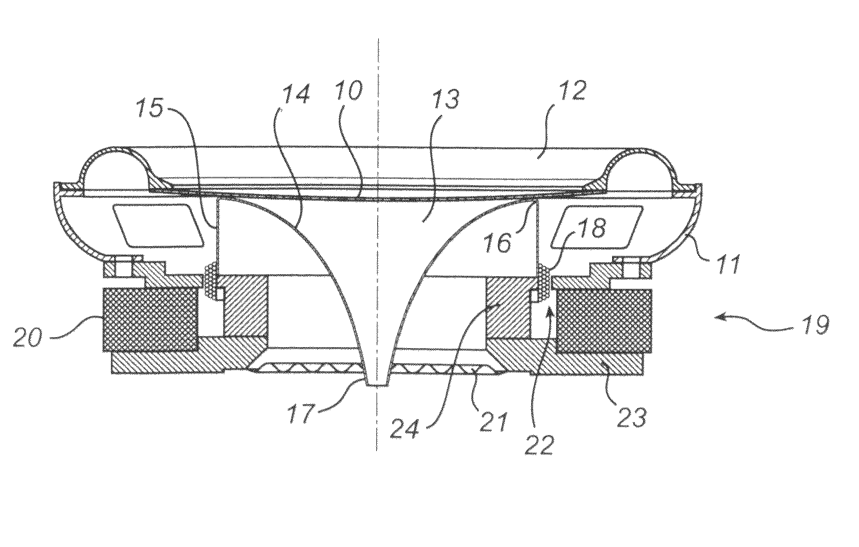
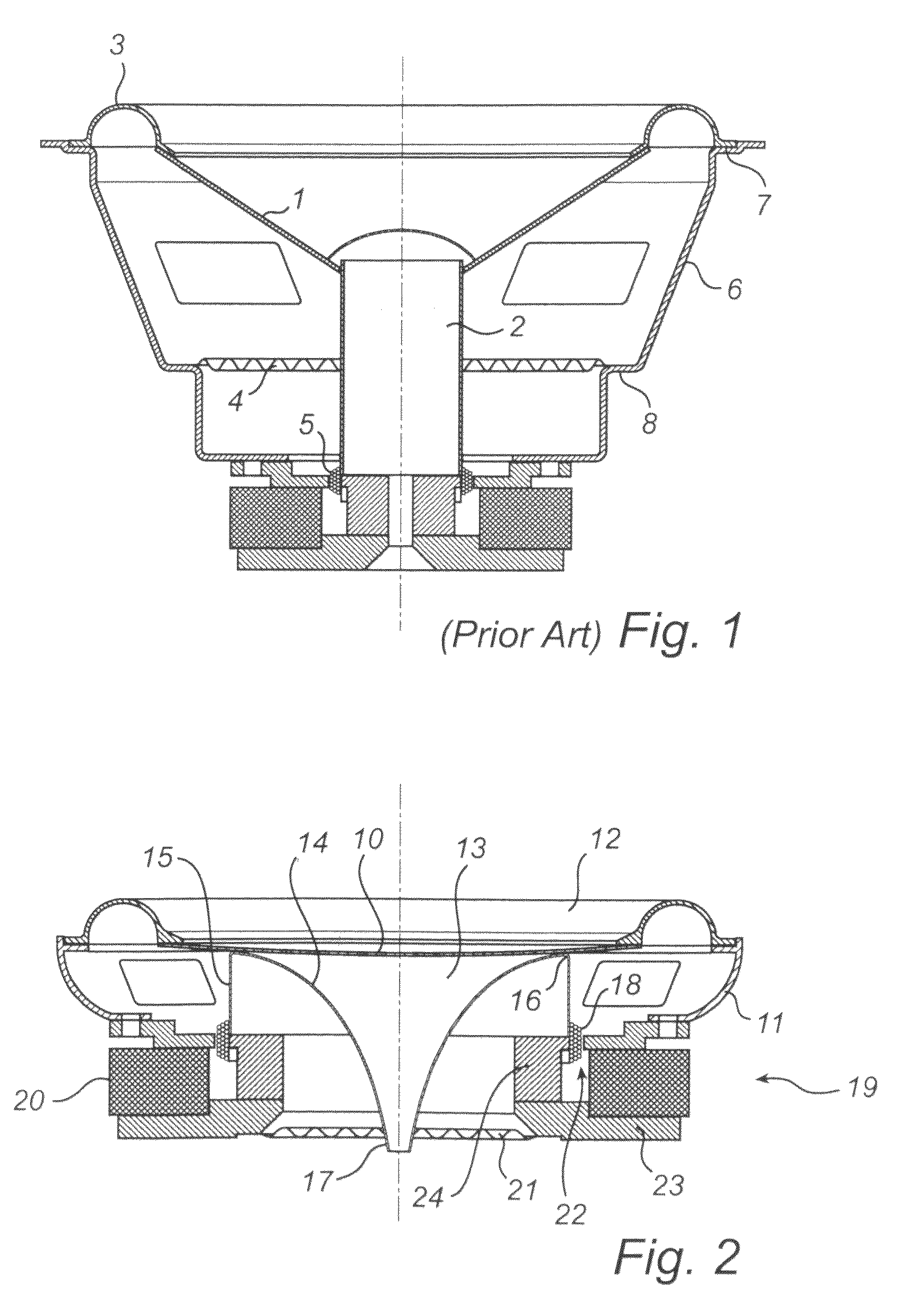
[0026]FIG. 2 shows a schematic cross section of a transducer according to a first embodiment of the invention. A diaphragm 10 is suspended in a basket enclosure 11 by a suspension 12 around its perimeter. The suspension may be e.g. a corrugated rubber annular rim. The back side (facing the interior of the loudspeaker) is attached to a coil former 13.

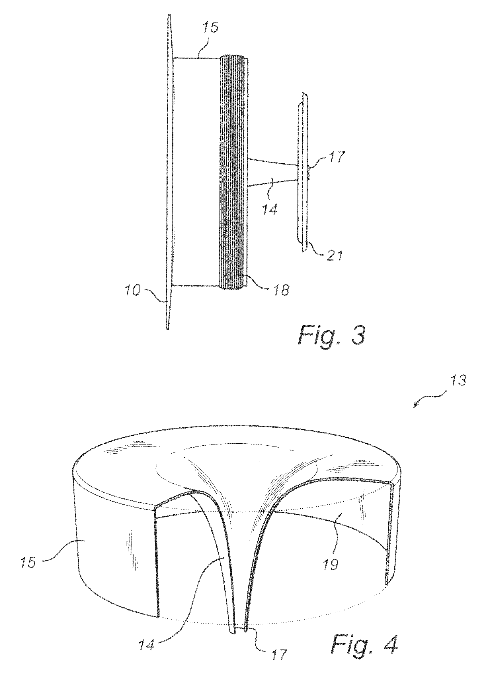
[0027]The coil former has two portions 14 and 15, arranged coaxially in relation to each other. In the illustrated embodiment, the first, inner portion 14 is shaped as a hyperbolic cone, and extends from an annular attachment 16 to the diaphragm to form a tapered end 17 at a distance from the diaphragm. The second, outer portion also extends from the annular attachment 16 and is essentially cylindrical in shape. The length of the inner portion is greater than, here approximately twice, the length of the outer portion.

[0028]A coil 18 is arranged around the periphery of the second coil former portion 15, and surrounded by a magnetic system...


PUM


Abstract

In one embodiment of the present invention, an electro-dynamic transducer is disclosed including a diaphragm, a first suspension suspending the diaphragm, a coil former attached to the diaphragm, the coil former having a first, inner portion, and a second, outer portion, arranged coaxially in relation to each other, a coil arranged around the outer coil former portion, a magnetic system, operable to magnetically cooperate with the coil, and a second suspension mounted between the inner coil former portion and the magnetic system. The new and improved way of placing the second suspension allows for a slim form factor, while stabilizing the system more than prior art designs. The transducer according to one embodiment of the present invention is less sensitive to rocking modes, and the gap in the magnet system can thus be made smaller.

Description

FIELD OF THE INVENTION[0001]The present invention relates to an electro-dynamic transducer with a slim form factor, i.e. that has a slim design. In particular, the invention relates to a loudspeaker used for applications like Automotive, Televisions, Displays, Flat Speakers, and Walls.BACKGROUND OF THE INVENTION[0002]A typical transducer architecture of an electro dynamic speaker is shown in FIG. 1. The speaker comprises a diaphragm 1 connected to a voice coil former 2. The diaphragm is suspended by a first suspension 3, and the voice coil former is suspended by a second suspsension 4, also referred to as the spider. A voice coil 5 is arranged around the bottom of the former 2, in the gap of a magnet system. The entire system is embedded in a basket 6, provided with flanges 7, 8 for supporting the suspensions 3, 4.[0003]When an alternating electrical current is brought to flow through the coil 5, a resulting force will move the diaphragm 1 and the former 2. The moving diaphragm move...

Claims


Application Information

Patent Timeline
Patent Type & Authority Patents(United States)
IPC IPC(8): H04R1/00
CPCH04R9/06
Inventor WEYREUTHER, MARCUS MICHAEL
Owner BANG & OLUFSEN ICEPOWER GI
Learn More