Method and system for monitoring a drilling operation

a drilling operation and monitoring system technology, applied in seismology for waterlogging, instruments, borehole/well accessories, etc., can solve the problems of unfavorable drilling time, increased drilling difficulty, and potentially serious operational errors, and achieve undesirable effects, the effect of reducing the drilling time caused by unwanted events

Active Publication Date: 2012-05-01
BAKER HUGHES INC
View PDF35 Cites 43 Cited by
  • Summary
  • Abstract
  • Description
  • Claims
  • Application Information

AI Technical Summary

Benefits of technology

[0011]g. repeating steps (a) to (e) over time, thereby to update the visual display of matching cases.
[0025]In the preferred embodiment of the present invention, we provide a software tool that is adapted to listen continuously to data streams from a drilling operation and process the data to generate a situation description for a current drilling situation in a form useful for automated continuous matching with a set of past cases stored in a knowledge database. The invention implements a case-based reasoning (CBR) approach to match the current drilling situation as defined by the situation description with one or more stored past cases having a degree of similarity above a predetermined threshold level. Matching cases are displayed to the drilling engineer as part of a graphical user interface as symbols on a case “radar”, allowing the drilling engineer to retrieve and view the details of a past case and take appropriate action based on drilling advice provided within the past case.

Problems solved by technology

As the world's reserves of fossil fuel diminish, wells are becoming increasingly difficult and correspondingly expensive to drill, and operational mistakes have potentially more serious, not to mention extremely expensive, effects.
Any loss of drilling time caused by unwanted events is undesirable.

Method used


Image

  • Method and system for monitoring a drilling operation
  • Method and system for monitoring a drilling operation
  • Method and system for monitoring a drilling operation

Examples


Embodiment Construction

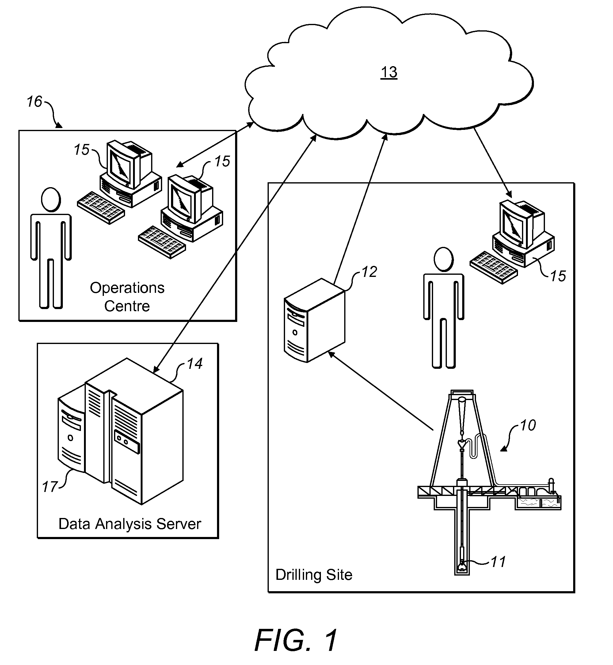
[0033]FIG. 1 is a simplified schematic of an offshore drilling site and associated communications and data processing network for monitoring a drilling operation in accordance with an embodiment of the present invention.

[0034]As shown in the Figure, sensors (not shown) located both on the drilling rig 10 and at a drill bit 11 produce data that are collected by a standard data collection service 12 also located on the drilling rig 10. The collected data is then transferred, in real-time, as one or more digital data streams over a communications network 13 to a remote data analysis server 14. The preferred transfer format and protocol is based on the industry WITSML format, which uses XML as a data format and web services over HTTPS as a protocol. The data analysis server 14 runs a software application which monitors the incoming data and performs data analysis.

[0035]Existing software visualisation tools for keeping track of data from these drilling logs help the personnel to perform ...


PUM


Abstract

The present invention provides a computer-implemented software tool that is adapted to listen continuously to data streams from a drilling operation and to process the data to generate a situation description for a current drilling situation in a form useful for automated continuous matching with a set of past cases stored in a knowledge database. The invention implements a case-based reasoning (CBR) approach to match the current drilling situation as defined by the situation description with one or more stored past cases having a degree of similarity above a predetermined threshold level. Matching cases are displayed to the drilling engineer as symbols on a case “radar”, allowing the drilling engineer to retrieve and view the details of a past case and take appropriate action based on drilling advice provided within the past case.

Description

BACKGROUND OF THE INVENTION[0001]Many industries, including the oil and gas industry, have access to large amounts of electronic data and information, and advanced software tools for displaying various types of information. As the amount of available data increases, the need for software tools to extract, or filter out, the relevant information in a given situation increases correspondingly.[0002]As part of their normal work, oil well drilling engineers and other operational personnel both offshore and in support centres onshore have at their disposal a large set of sophisticated sensor measurements and other drilling parameters. The bulk of this data are continuous (real time) data streams from the drilling operation. Software tools for keeping track of data from these drilling logs help the personnel to perform graphical comparisons through time-indexed or depth-indexed graphs. However, as powerful as these visualisation tools are, the drilling operation is fundamentally reliant o...

Claims


Application Information

Patent Timeline
Patent Type & Authority Patents(United States)
IPC IPC(8): G06F19/00G16Z99/00
CPCE21B44/00G06F19/00G06F17/00G01V9/00G06N5/022G16Z99/00E21B41/0092
Inventor AAMODT, AGNARSKALLE, PALGUNDERSEN, ODD ERIKSORMO, FRODESOLSTAD, JORGEN
Owner BAKER HUGHES INC
Why Eureka
Try Eureka