Supercharge Your Innovation With Domain-Expert AI Agents!

Bear trap with safety door

a safety door and trap door technology, applied in the field of traps, can solve the problems of heavy trap door, severe injury of cubs, and serious injury of people, and achieve the effect of reducing the risk of injury to people, and improving the safety of peopl

Active Publication Date: 2012-05-08
LYTLE ANDREW
View PDF63 Cites 6 Cited by
  • Summary
  • Abstract
  • Description
  • Claims
  • Application Information

AI Technical Summary

Benefits of technology

"The present invention is a bear trap that includes a hollow cylindrical shell with a front end opening and an end wall closing the opposite rear end. The trap has two upright channel guides on either side of the opening with a vertical channel opening facing each other. A vertically slidable trap door is positioned with its side extremities located in the channel openings. The trap door is adapted to fall by gravity to close the opening. A trigger mechanism associated with the trap door is provided so that when a bear seizes the bait located within the cylindrical shell, the trigger will allow the trap door to fall closing the front end opening. The bear trap also includes a pneumatic cylinder with a pneumatic piston movable from an extended position to a retracted position. The pneumatic cylinder is mounted to the trap door and positioned with the pneumatic piston extendable into a channel opening when the pneumatic piston is in the extended position to brake the falling trap door. A brake pad is mounted to the free end of the pneumatic piston and a pneumatic valve is provided for selectively directing compressed air from a reservoir to the pneumatic cylinder to move the pneumatic piston to the extended position. A trigger is positioned below the lower extremity of the trap door and is connected to the pneumatic valve for moving the pneumatic piston to the extended position when the trap door is falling and an object located in the front opening of the cylindrical shell pushes the trigger upwardly. The bear trap also includes an \"A\" frame mounted to the cylindrical shell over the front end opening and a pulley is mounted to the apex and a rope is secured to the trap door and threaded through the pulley leaving a free end which may be pulled to raise the trap door."

Problems solved by technology

The trap door used with this trap is very heavy, weighing approximately 80-100 pounds.
If the trap door falls on the cub, the cub will be severely injured.
Further, if a person were located in the opening, and the trap door released accidentally, the person could be severely injured as well.

Method used


Image

  • Bear trap with safety door
  • Bear trap with safety door
  • Bear trap with safety door

Examples


Embodiment Construction

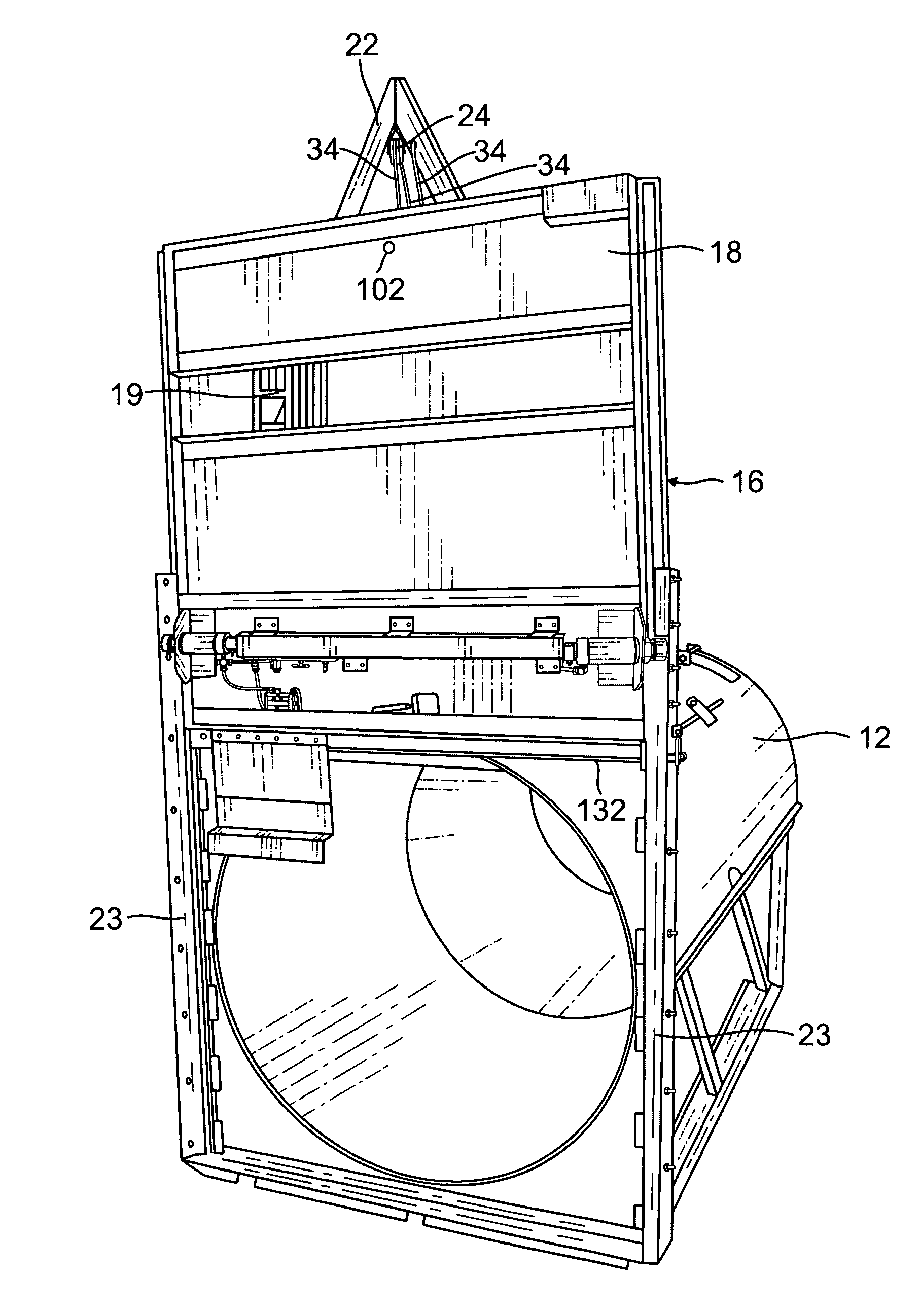
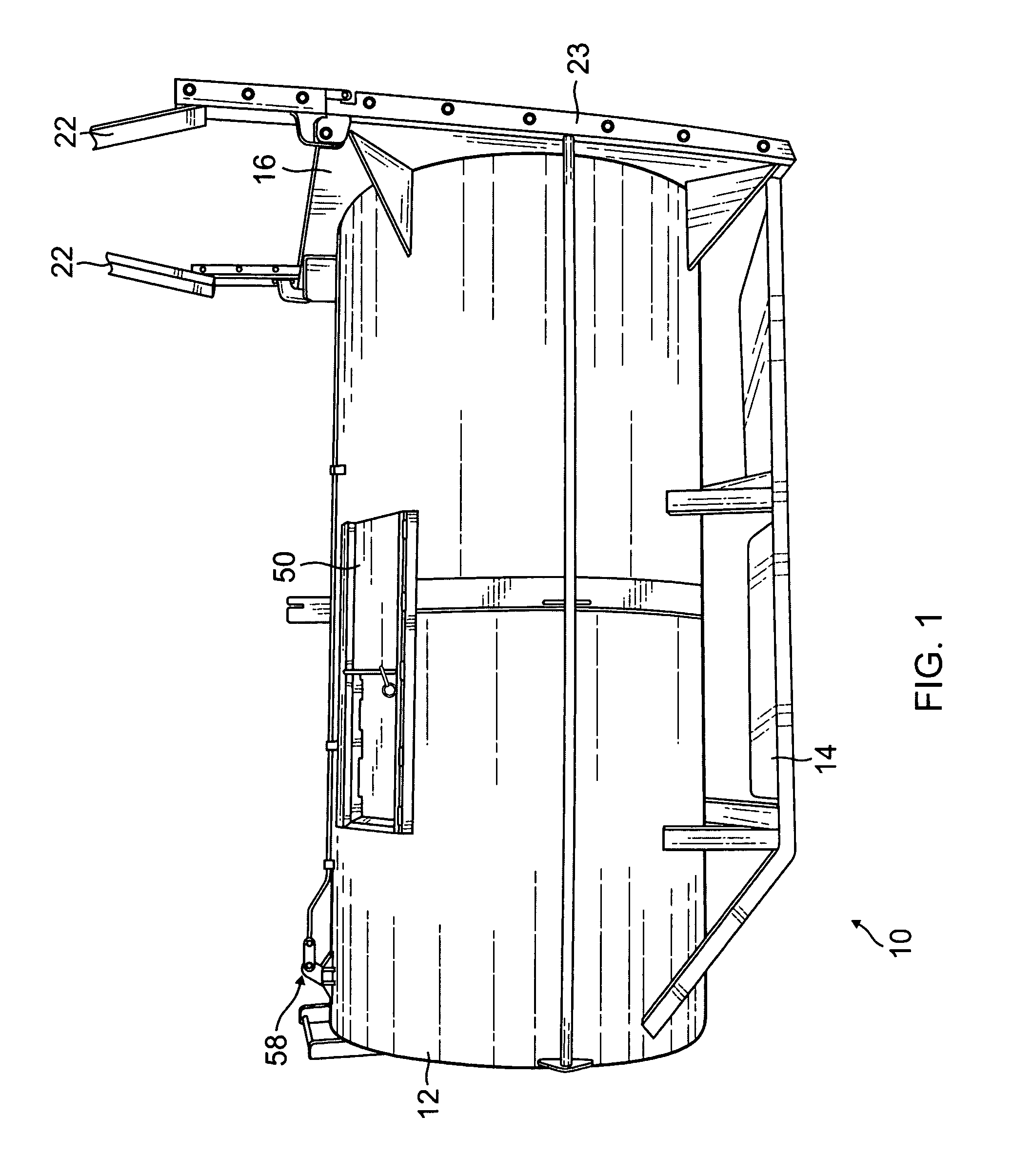
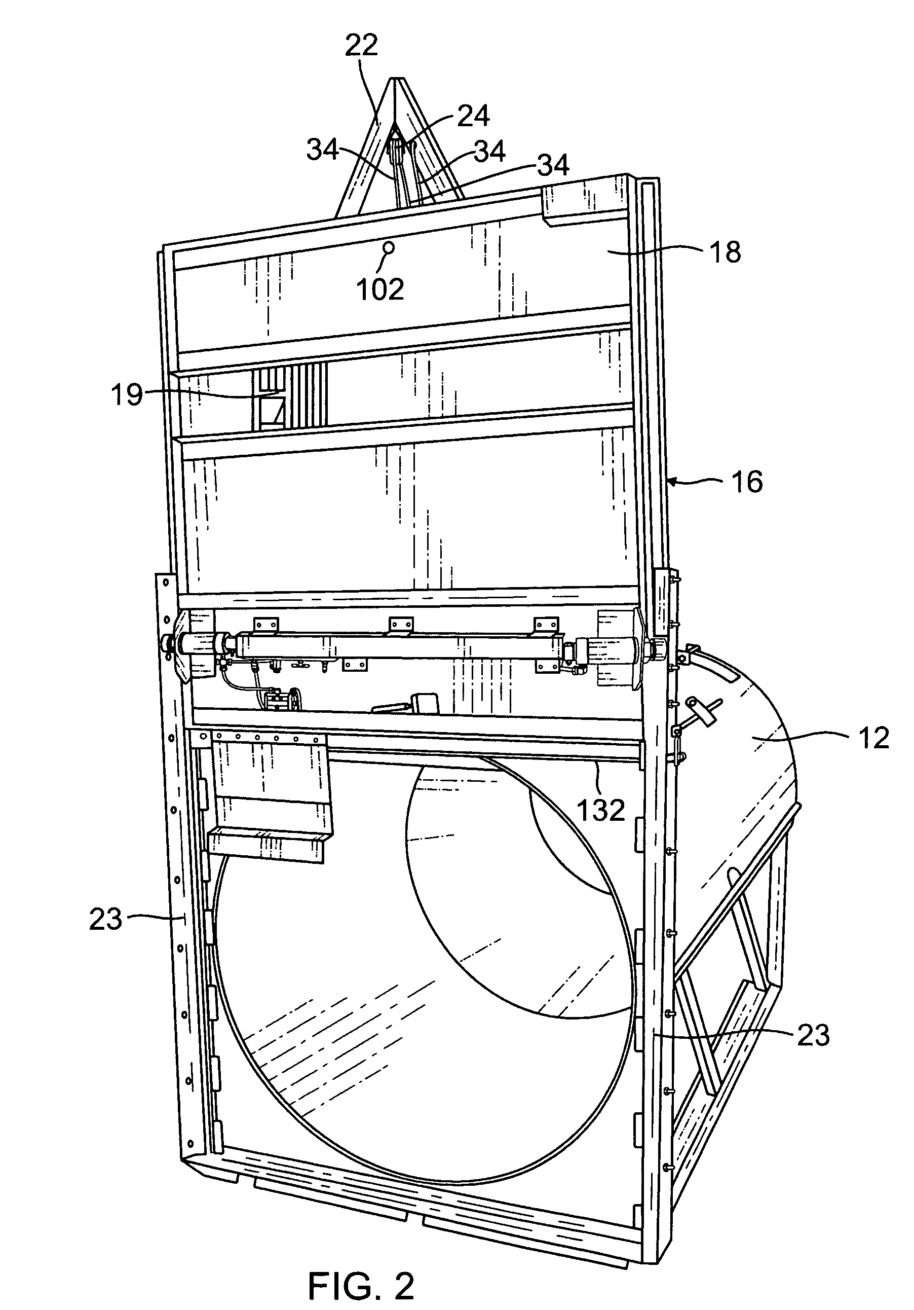
[0029]A bear trap 10 according to the present invention is shown in FIG. 1. The bear trap 10 includes a hollow cylindrical shell 12. This type of bear trap is known as a “culvert-style” trap and in a preferred embodiment is constructed of aluminum or steel. The cylindrical shell 12 is supported by a framed stand 14. The bear trap 10 includes a trap door 16 as shown in FIGS. 1 and 2. The trap door 16 includes a door panel 18 and a ventilation opening 19.

[0030]Vertical uprights 23 are provided on either side of trap door 16 as shown in FIGS. 1-3. Each of the uprights 23 are provided with vertical channels 20. A vertical flange 21 is provided on each lateral side of trap door 16 and rides in the channels 20 as shown in FIG. 3. In this manner, the trap door 16 slides up and down vertically within the channels 20. FIG. 2 shows the trap door 16 in an upward position thereby providing an entrance into the cylindrical shell 12. An “A”-frame 22 has free ends mounted to the upright channel me...


PUM


Abstract

A large animal trap including a hollow cylindrical shell having a front end opening. A vertically slidable trap door is positioned to close the front end opening. A trigger mechanism associated with the trap door is provided so that when a bear seizes the bait located within the cylindrical shell, the trigger will allow the trap door to fall closing the front end opening. This animal trap is further provided with a pneumatic braking assembly which stops downward movement of the trap door when an object is within the front end opening. The large animal trap is further provided with structure to allow a user to raise the trap door from a location away from the trap.

Description

[0001]This application claims the benefit of provisional application Ser. No. 61 / 072,089 filed Mar. 27, 2008.BACKGROUND OF INVENTION[0002]The present invention relates to a bear trap having a main trap door with a trigger mechanism that is tripped to close the main trap door and capture whatever is inside at the time the trigger was activated. The main trap door has an automatic braking system. The system will activate when an object is detected in the path of the door when it is falling to the closed position. This system will automatically stop the door from falling until the object has moved out of the path of the falling door.[0003]Live animal traps are well known such as described in U.S. Pat. No. 4,080,749 to Gilbaugh and U.S. Pat. No. 5,199,210 to Nastas. These animal traps include a rectangular cage closed at one end and having a trap door for closing the open end of the trap when an animal seizes the bait located inside the trap.[0004]The present invention is directed to a ...

Claims


Application Information

Patent Timeline
Patent Type & Authority Patents(United States)
IPC IPC(8): A01M23/20A01M23/00A01M23/16
CPCA01M23/20
Inventor FACKLAM, ROBERT
Owner LYTLE ANDREW
Features
  • R&D
  • Intellectual Property
  • Life Sciences
  • Materials
  • Tech Scout
  • Unparalleled Data Quality
  • Higher Quality Content
  • 60% Fewer Hallucinations
Learn More