Automatic transmission for a power tool

a transmission device and power tool technology, applied in the field of automatic transmission of power tools, can solve the problems of low torque operation mode and slow transmission assembly of high speed, and achieve the effect of more slowly rotating and more rapid rotation

Active Publication Date: 2012-05-08
TECHTRONIC POWER TOOLS TECHNOLOGY LTD
View PDF50 Cites 812 Cited by
  • Summary
  • Abstract
  • Description
  • Claims
  • Application Information

AI Technical Summary

Benefits of technology

[0014]The second driven gear is mounted onto the output shaft by the overrunning bearing or overrunning clutch whereby a clutch mechanism of said overrunning bearing establishes the low speed of operation of the power tool transmission assembly. When the first driven gear is disengaged, i.e. unlocked, from rotating with the output shaft and thus no longer delivers drive to the output shaft, the transmission assembly slows from its high speed, low torque mode of operation. Once the speed of operation reduces sufficiently, the clutch of the overrunning bearing enables drive to be delivered from the second driven gear to the output shaft to seamlessly establish the low speed, high torque mode of operation of the transmission assembly. This is advantageous in that the second driven gear can be constantly driven even when the transmission assembly is operating at its high speed of operation. This is because the over running bearing allows the second driven gear to rotate at a speed of operation lower than that of the output shaft of the transmission assembly. Furthermore, by unlocking the first driven gear from rotating with the output shaft when changing to the low speed of operation enables the first driven gear to be constantly driven because the first driven gear can continue to rotate at said high speed, but is no longer delivering any drive to the output shaft. Consequently, the transmission assembly does not require the axial movement of meshing gears to effect a change in speed of operation as is often found in conventional transmissions. Furthermore, the change in speed of operation of the transmission assembly of the invention can be effected whilst the transmission assembly is operating and can be effected in either direction, namely changed from high speed to low speed of operation or changed from low speed to high speed of operation whilst the transmission assembly is operating. There is no requirement to stop the transmission of the power tool when effecting a change in the speed of operation in either direction.
[0027]The transmission may be provided with first and second driven gears which are permanently driven by respective driving gears, but an overrunning bearing which couples the second driven gear to an output shaft of the transmission allows the second driven gear to rotate more slowly than the output shaft when the transmission is operating at a high speed of operation and a connector for engaging or disengaging the first driven gear from the output shaft, when operated to disengage the first driven gear from the output shaft, enables the first driven gear to rotate more quickly than the output shaft when the transmission assembly is operating at a low speed of operation.

Problems solved by technology

When the first driven gear is disengaged, i.e. unlocked, from rotating with the output shaft and thus no longer delivers drive to the output shaft, the transmission assembly slows from its high speed, low torque mode of operation.
Furthermore, by unlocking the first driven gear from rotating with the output shaft when changing to the low speed of operation enables the first driven gear to be constantly driven because the first driven gear can continue to rotate at said high speed, but is no longer delivering any drive to the output shaft.

Method used


Image

  • Automatic transmission for a power tool
  • Automatic transmission for a power tool
  • Automatic transmission for a power tool

Examples


first embodiment

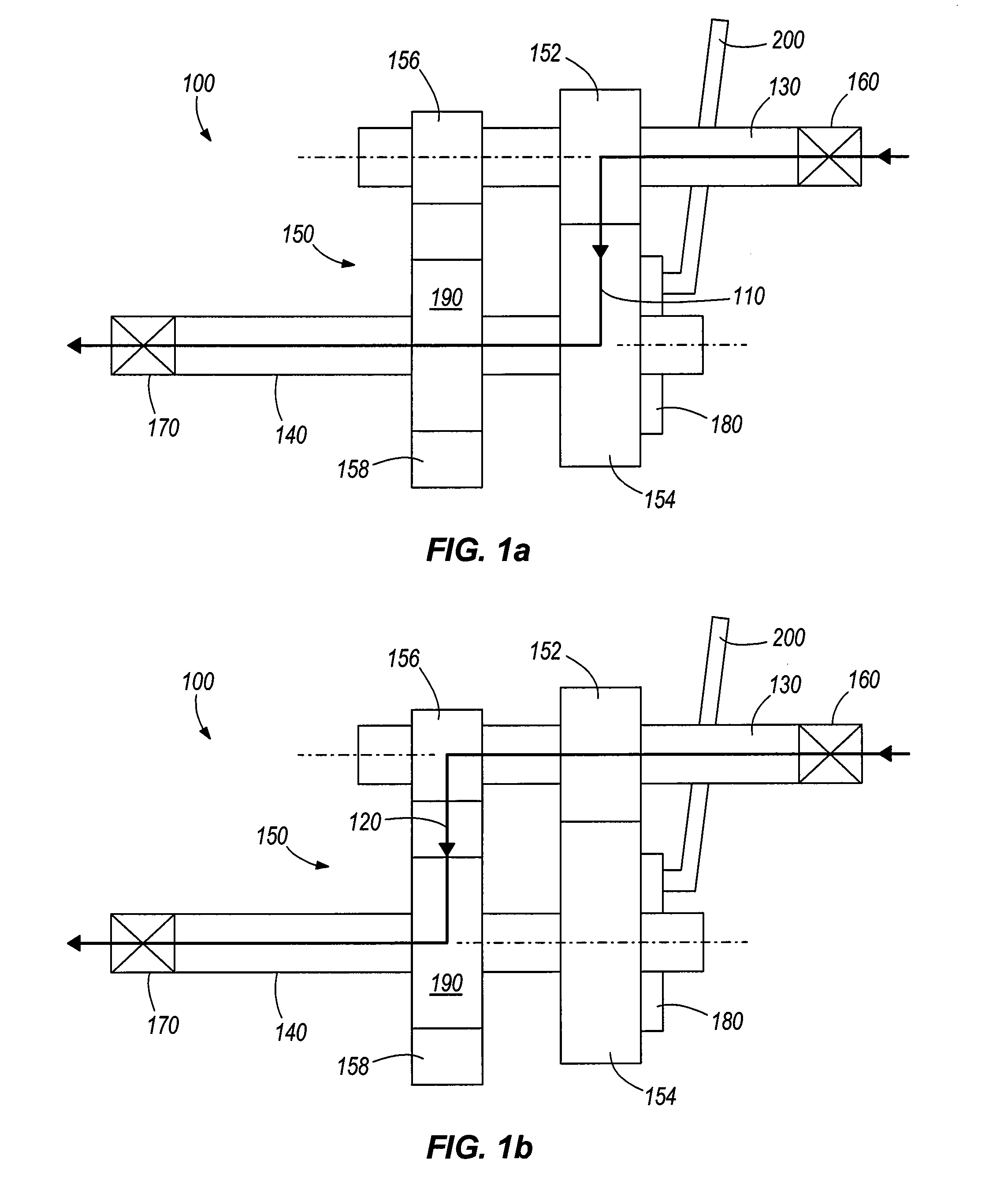
[0063]As illustrated by FIGS. 1a and 1b, in a first embodiment, the invention provides a manually operable transmission assembly 100 for a power tool comprising a first transmission path 110 constituting a high speed transmission path (FIG. 1a) and a second transmission path 120 constituting a low speed transmission path (FIG. 1b).

[0064]The transmission assembly 100 comprises an input shaft 130 powered by a motor (not shown) and an output shaft 140 powered by the input shaft via a gear train 150. The gear train 150 comprises a first driving gear 152 mounted on the input shaft 130 which meshes with a first driven gear 154 on the output shaft 140. The gear ratio established by the first driving gear 152 and the first driven gear 154 defines a high speed operation of the transmission assembly 100. The gear train 150 also comprises a second driving gear 156 also mounted on the input shaft 130 which meshes with a second driven gear 158 on the output shaft 140. The gear ratio of the secon...

second embodiment

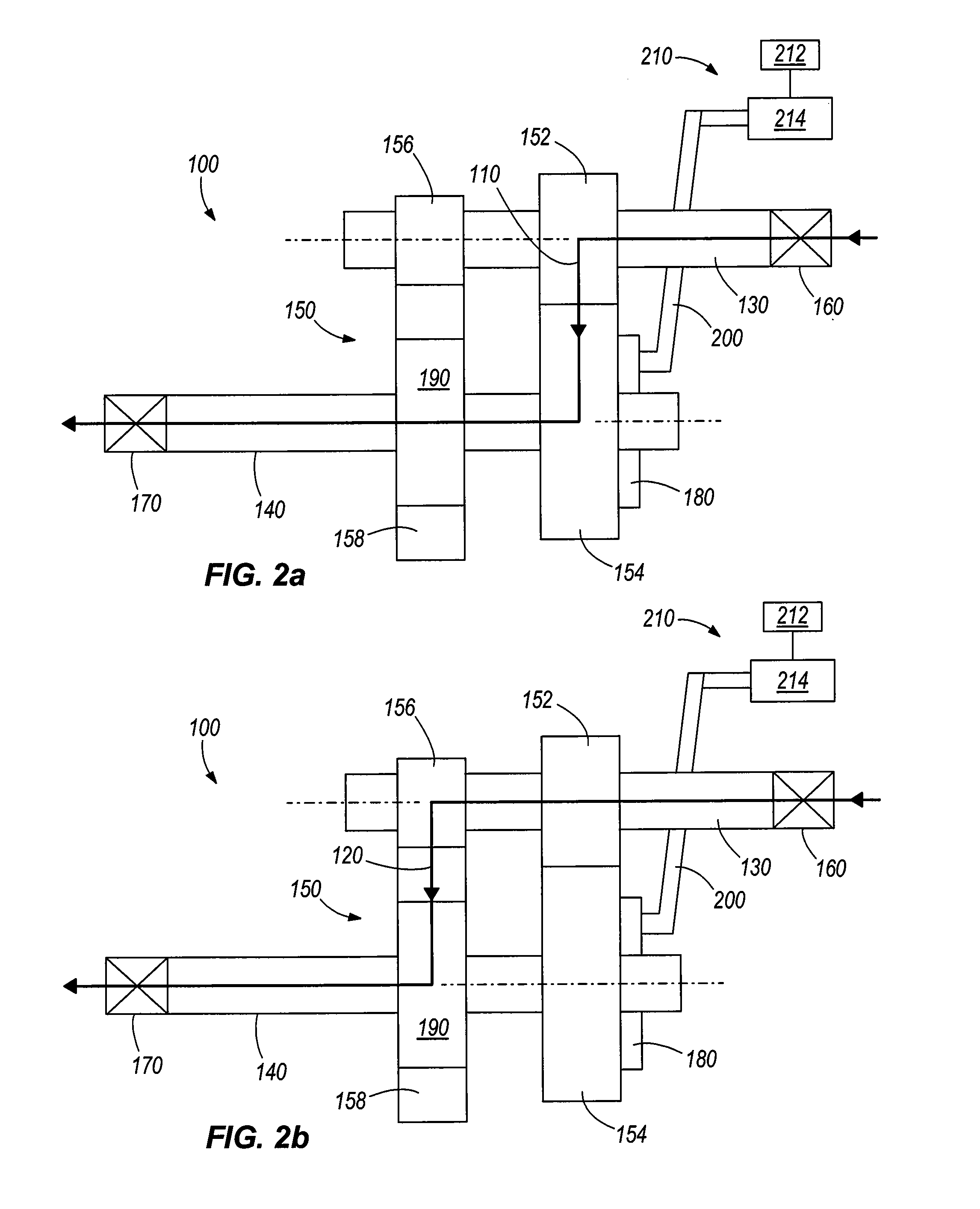
[0073]As illustrated by FIGS. 2a and 2b, in a second embodiment, the invention provides an automatically operable transmission assembly 100 for a power tool comprising a first transmission path 110 constituting a high speed transmission path (FIG. 2a) and a second transmission path 120 constituting a low speed transmission path (FIG. 2b).

[0074]The transmission assembly 100 of this embodiment is generally the same as that for the embodiment of FIGS. 1a and 1b and thus like numerals will be used to denote like parts. This embodiment differs, however, in that it automatically changes the speed of operation of the transmission assembly 100 in response to an amount of load exerted on the power tool motor.

[0075]A control mechanism 210 is provided for causing the connector 180 to disengage the high speed transmission path 110 in response to monitored operating current of an electric motor providing a driving torque to an input of the transmission. When disengaged, a driven gear 154 of the ...


PUM

PropertyMeasurementUnit
speedaaaaaaaaaa
currentaaaaaaaaaa
transmission assemblyaaaaaaaaaa

Abstract

A transmission assembly for a power tool comprises a first transmission path comprising a high speed transmission path and a second transmission path comprising a low speed transmission path. Driven gears of each transmission path are permanently driven during operation of the transmission. A controller is provided for engaging or disengaging the high speed transmission path in response to monitored operating current of an electric motor providing a driving torque to an input of the transmission. When disengaged, a driven gear of the high speed transmission path continues to be driven, but the driven gear is disengaged from an output of the transmission. Consequently, under these circumstances, the low speed transmission path is the ‘active’ transmission path providing a low speed, high torque drive to the transmission output. A clutch enables the low speed transmission path to operate at a lower speed than an output of the transmission assembly when the high speed transmission path is engaged and is providing a high speed, low torque drive to the transmission output.

Description

FIELD OF THE INVENTION[0001]The present invention relates to power tools, and more particularly to power tool transmissions.BACKGROUND OF THE INVENTION[0002]Some power tool transmissions are user-configurable to provide different speed outputs. For example, an operator of a multi-speed drilling machine may configure the drilling machine for high speed operation or low speed operation by actuating a mode switch on the drilling machine. However, this requires that the drilling machine be stopped, i.e. the transmission is stopped, in order to actuate the mode switch to effect a change in the speed of operation. It may even require removal of the drilling machine drill bit from the work piece prior to stopping of the drilling machine to effect the change in speed of operation in order to prevent locking or snagging of the drill bit in the work piece.[0003]Other power tools, such as circular saw machines only provide a single speed of operation. The load exerted on the circular saw machi...

Claims


Application Information

Patent Timeline
Patent Type & Authority Patents(United States)
IPC IPC(8): B25B21/00
CPCB23B45/008B23D47/12B23D51/16B25D16/003B25F5/001
Inventor HO, CHI HONG
Owner TECHTRONIC POWER TOOLS TECHNOLOGY LTD
Why Eureka
Try Eureka