Finned spindle liner

a spindle and lining technology, applied in the field of lining a hollow spindle, can solve the problems of reducing the service life requiring post-cast machining to remove defects, so as to reduce the diameter of the hollow spindle, increase the rotational inertia of the spindle assembly, and reduce the effort

Active Publication Date: 2009-07-07
HAAS AUTOMATION
View PDF11 Cites 0 Cited by
  • Summary
  • Abstract
  • Description
  • Claims
  • Application Information

AI Technical Summary

Benefits of technology

[0006]In accordance with the present invention, a finned spindle liner is inexpensively produced by extruding a material such as high density polypropylene, polyvinyl chloride (“PVC”), nylon lubricated with molybdenum disulfide or the like. The finned shape of the liner allows it to reduce the diameter of the hollow spindle of a metal turning machine tool without greatly increasing the rotational inertia of the spindle assembly. Because the fins are oriented in axial, rather than annular, contact with the inner surface of the spindle, insertion and removal of the finned liner can be accomplished with reduced effort. The fins also provide vibration damping, permitting the spindle to rotate more quickly.

Problems solved by technology

These conventional approaches to lining a hollow spindle experience a number of problems.
Because of the wide variety of stock piece and spindle shapes and sizes, it can become prohibitively expensive to manufacture a comprehensive set of spindle liners capable of reducing a variety of spindle sizes to a variety of stock piece sizes and shapes.
Further, the manufacture of cast spindle liners requires expensive and time-consuming post-cast machining to remove defects and improve tolerances.
Further, the mass of conventional spindle liners greatly increases the moment of inertia of the spindle, resulting in additional wear on the spindle and the machine tool.
Finally, the nature and extent of the contact area between conventional spindle liners and the spindle may render insertion and removal of the liner difficult.

Method used


Image

  • Finned spindle liner
  • Finned spindle liner
  • Finned spindle liner

Examples


Embodiment Construction

[0019]In the following detailed description, numerous specific details are set forth to provide a full understanding of the present invention. It will be apparent, however, to one ordinarily skilled in the art that the present invention may be practiced without some of these specific details. In other instances, well-known structures and techniques have not been shown in detail to avoid unnecessarily obscuring the present invention.

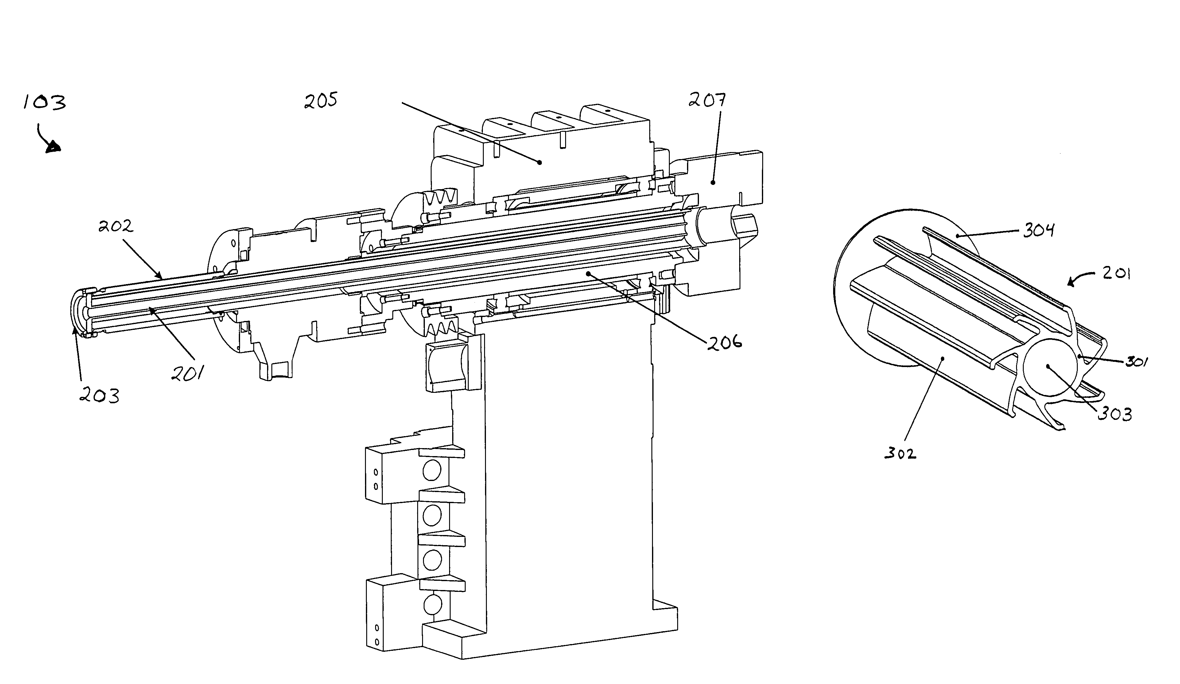
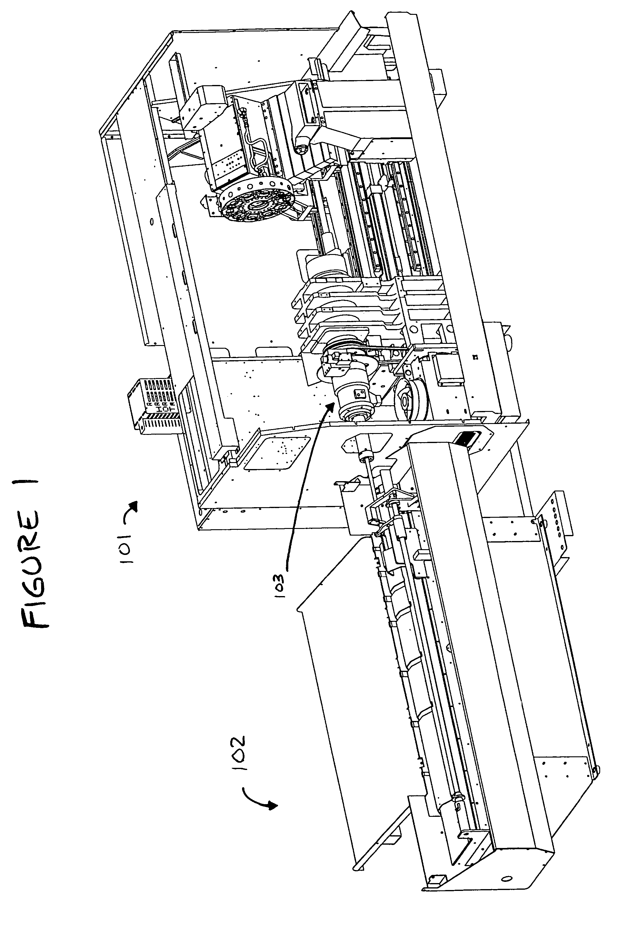
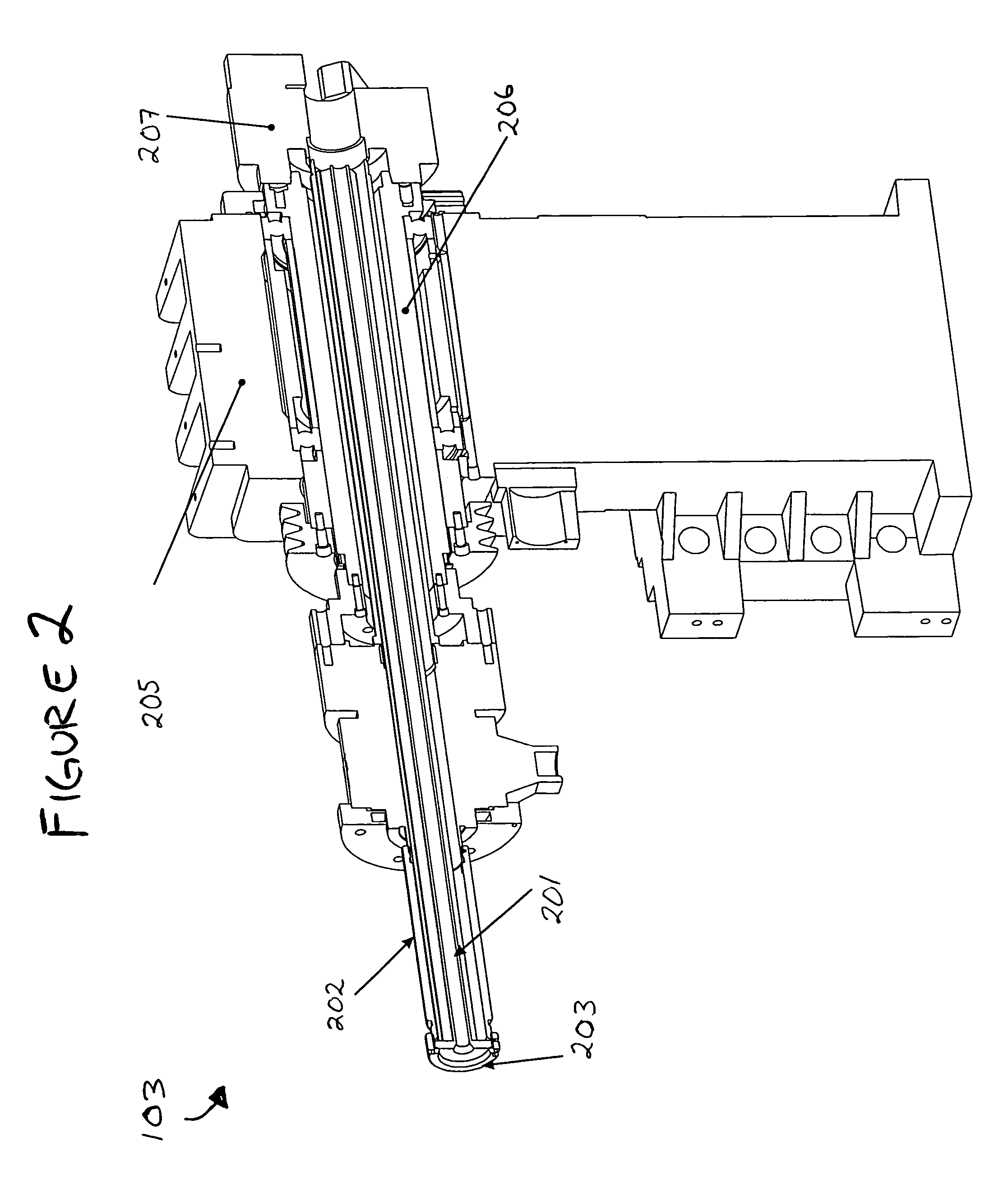
[0020]FIG. 1 depicts a metal turning machine tool 101 and an automatic stock feeder 102 in which a spindle liner of the present invention can be used. Machine tool 101 includes spindle assembly 103, which is illustrated in greater detail in the partial cut-away view of FIG. 2. Spindle assembly 103 includes a spindle housing 205, through which passes a spindle 206, in which is disposed a spindle liner 201. Spindle liner 201 is secured to spindle 206 by connecting retaining device 203 to liner adapter 202. Retaining device 203 may be a retainer plate, a ret...


PUM

PropertyMeasurementUnit
axial lengthaaaaaaaaaa
densityaaaaaaaaaa
outer diameteraaaaaaaaaa

Abstract

A spindle liner including an axial sleeve having an axial length and an inner bore for receiving a stock piece is provided. The spindle liner further includes fins extending radially outward from the axial sleeve for supporting the axial sleeve within a spindle. Each fin extends along the axial length of the spindle liner. The spindle liner may be extruded from a high density material such as high density polypropylene, polyvinyl chloride or nylon and molybdenum disulfide. The spindle liner may further include an retaining flange attached to a distal end of the spindle liner.

Description

FIELD OF THE INVENTION[0001]The present invention generally relates to bar feeding systems for metal turning machine tools and, more particularly, relates to spindle liners for bar feeding systems.BACKGROUND OF THE INVENTION[0002]Metal turning machine tools such as lathes frequently include a hollow spindle through which bar stock or stock pieces of different diameters are fed to a cutting head. When a stock piece with a diameter less than the inner diameter of the hollow spindle is fed through the spindle, it is desirable to use a spindle liner to constrain the stock piece to a concentric rotation with the spindle, to prevent undesirable wobble or “whip.”[0003]One conventional spindle liner takes the form of a cylindrical reducing tube with an inner diameter and shape configured to slidably receive and support a stock piece, and an outer diameter equal to or slightly less than that of the inner diameter of the spindle. Such a conventional reducing tube is either cast or machined fr...

Claims


Application Information

Patent Timeline
Patent Type & Authority Patents(United States)
IPC IPC(8): B23B13/08B23B19/02
CPCB23B13/08B29C47/0009B23B2226/33Y10T82/2562Y10T82/2595B29C47/00B29C48/00B29C48/03Y10T292/91
Inventor NUNES, JAMES A.GELDERMAN, CURTTANDROW, WILLIAMROCKSVOLD, NICHOLAS M.
Owner HAAS AUTOMATION
Why Eureka
Try Eureka