Legged robot and control method of legged robot

a robot and control method technology, applied in the field of legged robots and control methods of legged robots, can solve the problems of inaccurate detection of floor reaction force, increase in the number of triaxial force sensors that cannot be used to calculate floor reaction, and inability to accurately obtain floor reaction force, etc., to achieve the effect of obtaining the floor reaction force momen

Inactive Publication Date: 2012-05-08
TOYOTA JIDOSHA KK
View PDF16 Cites 27 Cited by
  • Summary
  • Abstract
  • Description
  • Claims
  • Application Information

AI Technical Summary

Benefits of technology

[0014]The invention provides a legged robot and a control method of the legged robot with which contact between a sole and a road surface is maintained while effectively obtaining a floor reaction force moment for righting a trunk of the robot, even on uneven ground.
[0016]By detecting the falling direction of the trunk of the robot and selecting three sole distance sensors for attaining a target value based on the detection result, contact between the sole and the road surface can be maintained while effectively obtaining a floor reaction force moment for righting the trunk (body) of the robot. Hence, by receiving the floor reaction force moment from the sole while keeping a supporting leg in close contact with the floor surface, stabilization control for righting the trunk of the robot can be executed easily, and as a result, the legged robot can walk over uneven ground without falling over. Note that the gait data are data for causing the robot to walk, and include a target position / attitude of the body and a target position / attitude of the foot portion. The legged robot according to the invention is caused to perform a walking operation by first bringing the foot part of the leg portion into contact with a floor surface so as to serve as a supporting leg, and then driving the leg portion such that the floor surface is pushed by the sole of the foot, thereby lifting up the entire leg portion (the entire robot). The driven leg portion becomes a lifted leg and the other leg portion becomes the supporting leg, and by switching the lifted leg and supporting leg repeatedly, a walking operation can be performed.
[0026]By detecting the falling direction of the trunk of the robot and selecting three sole distance sensors for attaining a target value based on the detection result, contact between the sole and the road surface can be maintained while effectively obtaining a floor reaction force moment for righting the trunk of the robot. Hence, by receiving the floor reaction force moment from the sole while keeping the supporting leg in close contact with the floor surface, stabilization control for righting the trunk of the robot can be executed easily, and as a result, the legged robot can walk over uneven ground without falling over.

Problems solved by technology

However, with the techniques described in Japanese Patent No. 3574952 and Japanese Patent No. 3569768, it may be impossible to obtain the floor reaction force accurately when more than three sensors come into contact with the road surface.
In this case, it may be impossible for all of the sensors to contact the road surface, depending on the road surface condition, leading to an increase in the number of triaxial force sensors that cannot be used to calculate the floor reaction force, and as a result, the floor reaction force cannot be detected accurately.
Further, when three sensors are used, an actual convex closure foamed by a contact part between the sole and the road surface decreases in size, leading to a reduction in the size of a stable region in which a Zero Moment Point (to be referred to simply as “ZMP” hereafter) can exist, and as a result, the robot is more likely to fall over.
Hence, providing more than three sensors leads to redundancy, while three sensors are insufficient.
Furthermore, with the technique described in JP-A-2001-353686, the distance between the road surface and the sole in the sensor position cannot physically be set at zero when a part other than the sensor contacts the road surface.
In other words, it may be impossible to set a measurement height value of all of the distance sensors at zero, depending on the road surface condition.
However, considering that a plane is determined by three points, one contact location between the road surface and the sensor becomes redundant if distance sensors are disposed in the four corners.
If the number of distance sensors is redundant, the values of all of the distance sensors cannot be set at desired values when the sole of the robot steps on a complicated irregularity.
Hence, it may be impossible to bring all four points on the sole of the supporting leg into close contact with the road surface, depending on the irregularity condition of the road surface.
When control is performed in this case to align the values of all of the sole distance sensors with desired values, for example when the sole is corrected to minimize a square error of the distance, control may be performed to an extremely unstable condition, for example such that the sole lands on the road surface on the diagonal.
In other words, when an attempt is made to align the values of all of the distance sensors with target values, an unstable condition may conversely be maintained.
Hence, when the trunk of the robot tilts while the sole is not in close contact with the road surface, the robot is unable to obtain a floor reaction force moment for correcting the tilt and may fall over as a result.
In a constitution where only three sole distance sensors are selected, it may be impossible to bring the sole of the supporting leg into close contact with the road surface depending on the falling direction of the trunk, leading to instability.
The reason for this is that when the tilt direction of the trunk of the robot and the direction of an irregularity on the road surface are close, control is performed such that the sole lands on the road surface on a diagonal, similarly to the case described above, leading to an unstable condition.
Hence, according to the legged robots in the related art, because it is difficult to maintain contact between the sole and the road surface while effectively obtaining a floor reaction force moment for causing the trunk of the robot to an inverted pendulum state, the robot might not walk with stability and without falling over depending on the road surface condition.

Method used


Image

  • Legged robot and control method of legged robot
  • Legged robot and control method of legged robot
  • Legged robot and control method of legged robot

Examples


first embodiment

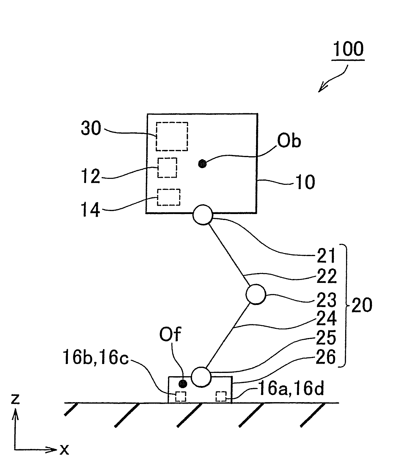
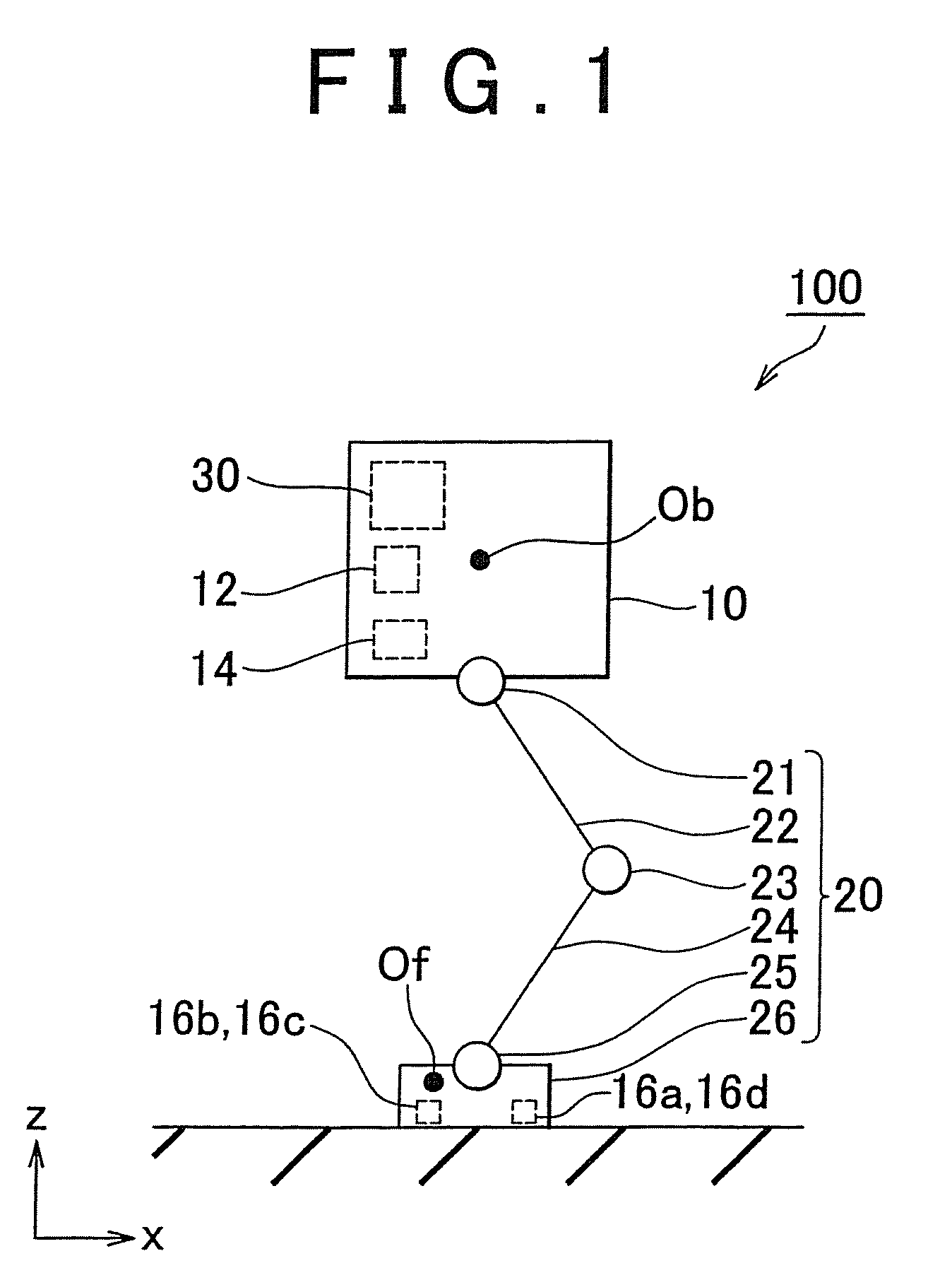
[0047]A legged robot includes a body, a leg portion connected to the body, a foot portion provided on a lower end of the leg portion, a falling direction detection unit that detects a falling direction of the body, a control unit that controls drive of a joint of the leg portion, and a distance detection unit that detects a distance between a sole of the foot portion and a road surface. Here, the distance detection unit includes at least three distance sensors provided on the sole of the foot portion. The control unit of the legged robot includes distance sensor selecting means for selecting a distance sensor, and gait data correcting means for correcting gait data based on a detection signal from the distance sensor selected by the distance sensor selecting means. The distance sensor selecting means selects three distance sensors from among the distance sensors based on a detection result from the falling direction detection unit.

[0048]When the walking robot walks on uneven ground...

second embodiment

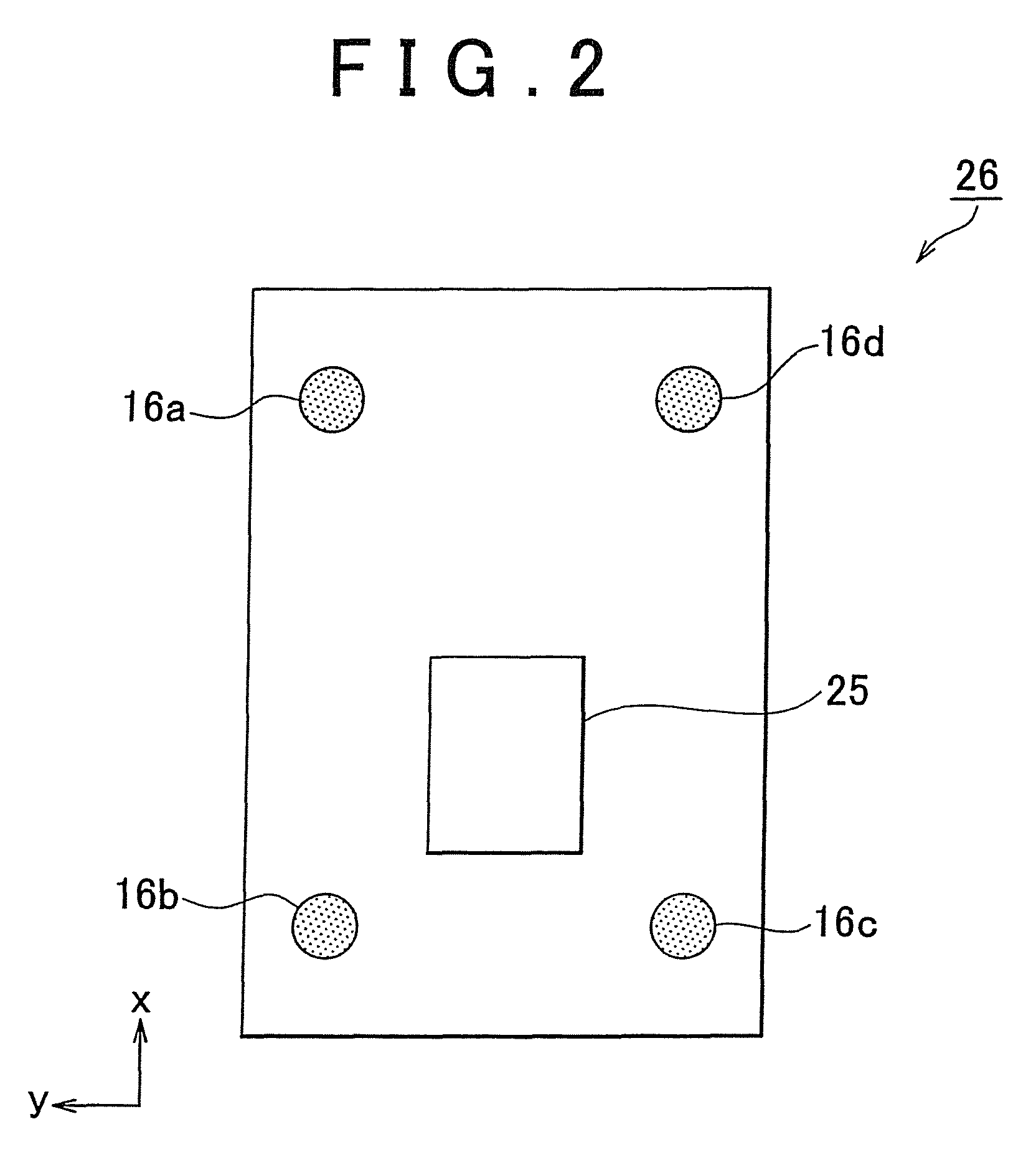
[0101]FIG. 12 is a view illustrating the constitution of the foot link 26 on the robot 100 according to the The foot link 26 includes a toe portion 26a and a heel portion 26b connected to the toe portion 26a via a toe joint 27. By driving the toe joint 27 during a walking operation of the robot 100, the heel portion 26b can be raised while keeping the toe portion 26a in contact with the road surface. In other words, the robot 100 can be caused to stand upright by grounding only the toe portion 26a while the heel portion 26b is raised.

[0102]As shown in FIG. 12, the toe portion 26a and heel portion 26b take a substantially rectangular shape when seen from the upper surface. The four distance sensors 16a, 16b, 16c, 16d are provided respectively near the four corners of the toe portion 26a. Here, the two distance sensors 16a and 16d are provided on the toe side of the toe portion 26a, while the two distance sensors 16b and 16c are provided on the heel portion direction side. The distan...


PUM


Abstract

A legged robot includes: a body; a leg portion; a foot portion; a falling direction detection unit that detects a falling direction of the body; a control unit; and a distance detection unit that detects a distance between a sole of the foot portion and a road surface. The distance detection unit includes at least three distance sensors provided on the sole, and the control unit includes distance sensor selecting means for selecting a distance sensor and gait data correcting means for correcting gait data based on a detection signal from the distance sensor selected by the distance sensor selecting means. The distance sensor selecting means selects three distance sensors among the distance sensors based on a detection result of the falling direction detection unit.

Description

[0001]This is a 371 national phase application of PCT / IB2008 / 003245 filed 22 Oct. 2008, claiming priority to Japanese Patent Application No. 2007-278107 filed 25 Oct. 2007, the contents of which are incorporated herein by reference.BACKGROUND OF THE INVENTION[0002]1. Field of the Invention[0003]The invention relates to a legged robot and a control method of the legged robot.[0004]2. Description of the Related Art[0005]To ensure that a legged mobile robot moves with stability and without falling over, a supporting leg of the robot must be brought into close contact with a road surface. It is also desirable to suppress unforeseen outside disturbance forces from road surface irregularities when a lifted leg of the robot is grounded. It is therefore important to control the relationship between the soles of the robot and the road surface in accordance with a target.[0006]In related art, many techniques of disposing a sensor on the soles of the robot and aligning an output value of the s...

Claims


Application Information

Patent Timeline
Patent Type & Authority Patents(United States)
IPC IPC(8): B62D51/06G05B19/00B25J5/00B25J13/08
CPCB62D57/032B25J5/00B25J13/08
Inventor SHIMADA, HIROSHI
Owner TOYOTA JIDOSHA KK
Why Eureka
Try Eureka