
Probe actuated bottle cap and liner

a technology of actuation and bottle caps, applied in the field of bottle caps, can solve the problems of failure of the probe and the inner cap or plug to re-engage, the inner cap will not engage the probe correctly, and the use of valved bottle caps, etc., to achieve less expensive manufacture of the probe, less costly use, and easy disengagement from the probe

Active Publication Date: 2012-05-08
BLACKHAWK MOLDING
View PDF6 Cites 4 Cited by
  • Summary
  • Abstract
  • Description
  • Claims
  • Application Information

AI Technical Summary

Benefits of technology

[0007]The closures described and claimed herein not only provide the benefits of the current valved bottle caps in that they prevent bacteria transfer to the dispensing reservoir and spillage during bottle installation, but they also solve some of the problems associated with the valved bottle caps. First, these caps will have no “floaters” because there are no removable parts. Second, these caps will be closed when removed from the dispensing system, at least visually. Third, these caps will disengage from the probe more easily because they will not grip the probe as tightly as the valved bottle caps having extended central tubes, and there will be no inner cap or plug that has to snap into place on the probe. Fourth, these caps will be is less costly to use because the inner cap is eliminated. Elimination of the inner cap will not only save plastic, it will also save an entire molding operation, an assembly step, and equipment operation and maintenance. Further, it may be less expensive to manufacture the probe because the retaining slot on the end is no longer needed. Last, these caps are compatible with various manufacturer's probes that have an industry standard diameter of about 0.75 inches.
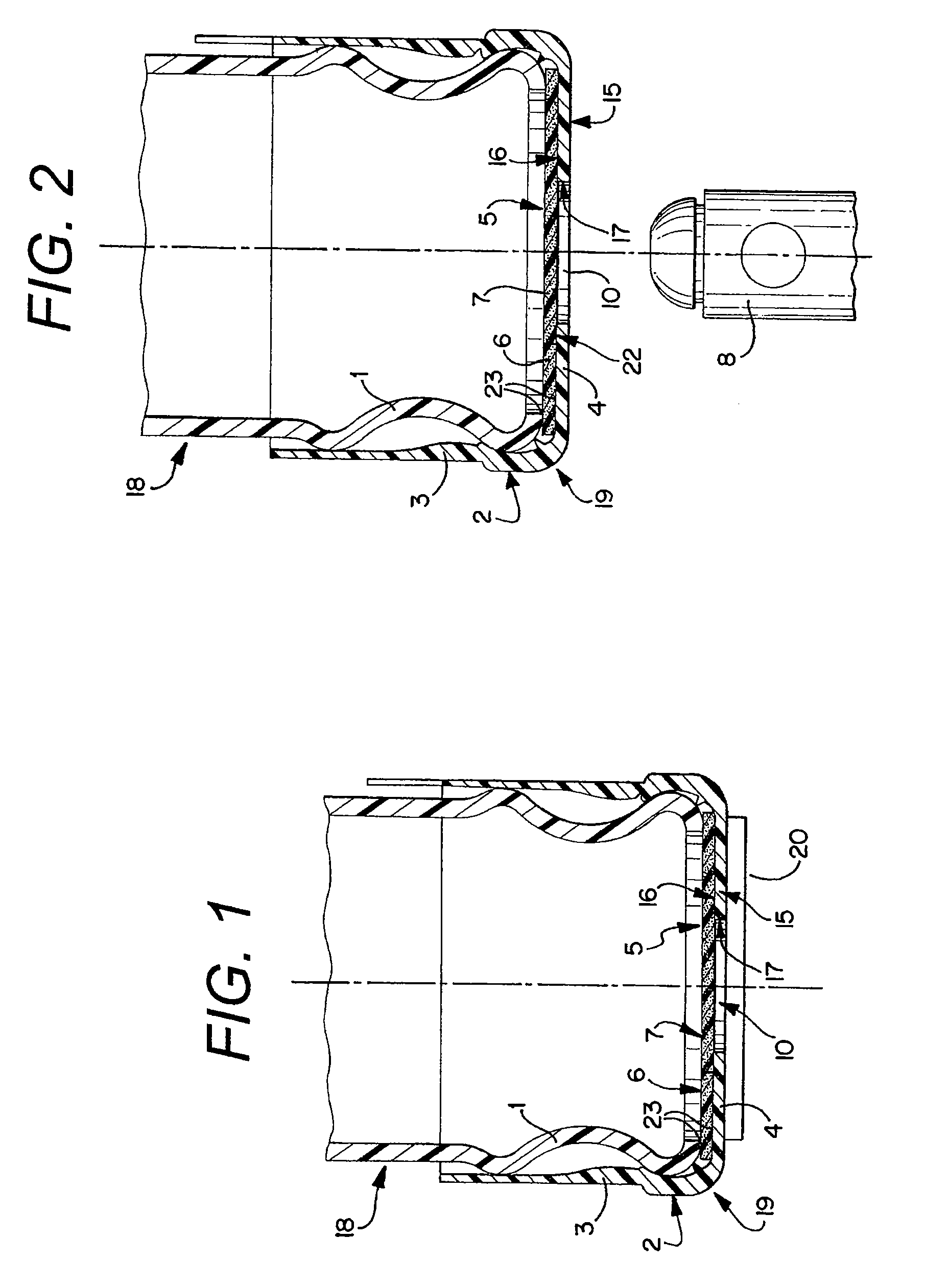
[0008]The caps described herein are comprised of two parts. The first part is a main cap body, and is comprised of a generally cylindrical skirt extending from and integrally formed with an annular top. The opening in the annular top is designed to receive a dispensing probe of standard diameter. The diameter of the opening is not greater than the diameter of the dispensing probe such that a seal is formed when the bottle cap is lowered onto the probe. Optional or alternative means for sealing against the probe include increasing the thickness of the lid in the axial direction at the edge of the opening, reducing the thickness of the lid in the axial direction at the edge of the opening, and attaching a lip seal at the edge of the opening.
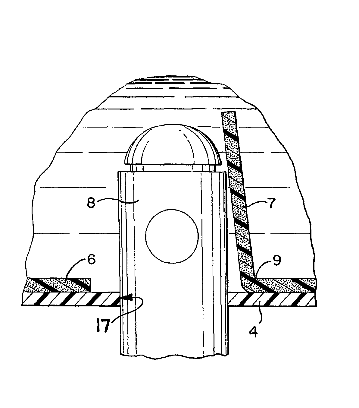
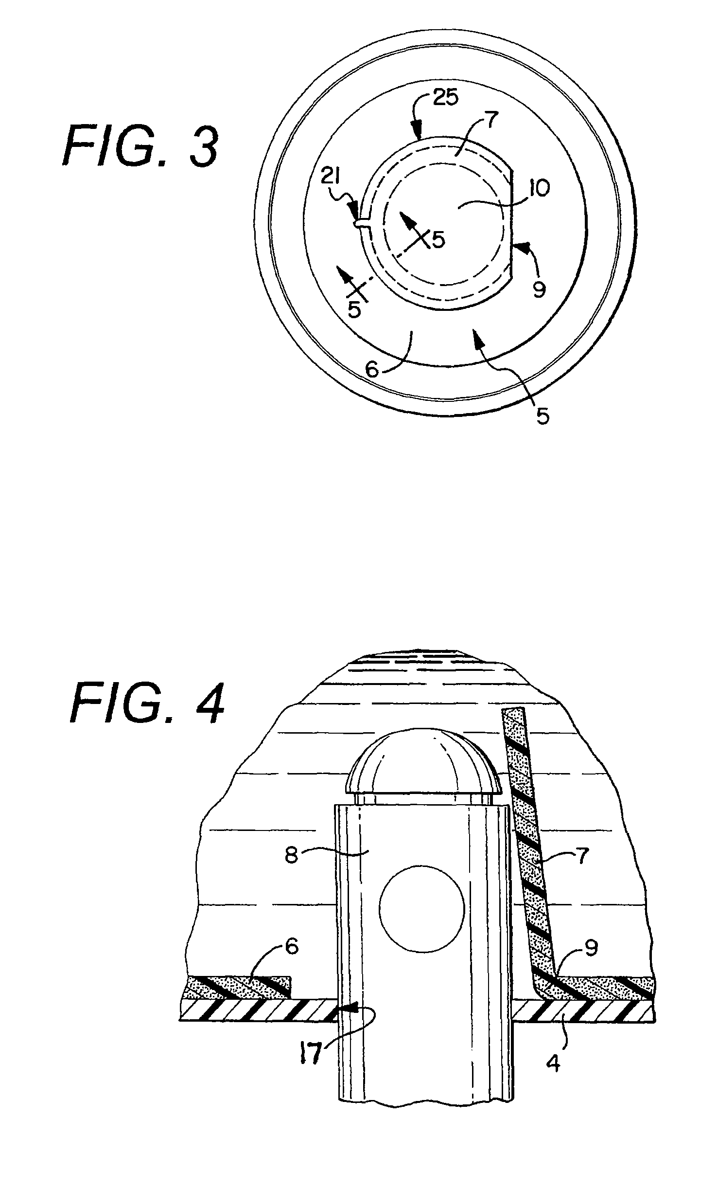
[0009]The caps described herein have an outer skirt and a lid with a central opening. From the outside, a membrane or other label covers the opening in the lid. The cap includes a liner connected to the underside of the lid of the cap. The liner includes an inner movable part covering the opening from the inside of the cap, and an outer part gripped between the underside of the lid and the container. When gripped between the lid and the neck of the container, the outer part not only holds the inner movable part in place at the opening but also provides a seal to prevent leakage along the skirt and the container. The inner movable part is larger than the opening to prevent liquid flow through the opening when the container is turned on its side during transit and when the container is inverted during installation onto the dispensing system. The static pressure of the container contents will tend to seal the inner movable part against the underside of the lid effectively preventing flow through the opening. Optionally, a raised surface can be molded onto the inside surface to concentrate the static force at a reduced contact area between the inner movable part and the lid. One of the connecting sections is relatively large and serves as a hinge for the inner movable part such that the inner movable part forms a flap as the bottle cap is lowered onto the probe. Optional small connecting sections could take the form of frangible ties which hold the inner movable part in place until they are broken by lowering the cap onto the probe. Alternatively, the connecting sections could remain attached to the inner movable part and be made out of an elastic material such that the connecting sections stretch when the cap is lowered onto the probe.
[0010]An optional but preferable feature is a protective tamper evident membrane seal which is attached to the top of the lid, such as that shown in U.S. Pat. No. 5,904,259. The tamper evident seal prevents dirt from coming into contact with the parts of the cap which then come into contact with the probe.

Problems solved by technology

There are some problems associated with the use of valved bottle caps.
Occasionally, an inner cap will not engage correctly with the probe when the bottle is installed on a water dispensing system or with the central tube when the bottle is removed from the water dispensing system.
Even if the probe and inner cap or plug successfully engage upon the installation of a full bottle onto the dispenser, it is still possible for there to be a failure for the probe and inner cap or plug to re-engage when the bottle is removed from the dispenser.
When a bottle contains such debris, the bottler who wants to re-use the bottle has a significantly more difficult time cleaning the bottle, as compared to a bottle that has not been used as a trash container.
Users have also experienced difficulty in removing the bottle from the dispensing system, especially when pulling the bottle off at an angle.
The length of the central tube may create too great a grip on the probe making removal of the bottle difficult.
When this occurs, greater force may be needed to remove the bottle, which may then cause the bottle to disengage from the probe suddenly causing the bottle to hit the user on the face.
Also, valved bottle caps can be costly compared to a cap molded as a single component.
In addition, providing the inner cap or plug as a separate component means that there is both labor and equipment needed to pre-attach the inner cap or plug to the central tube.

Method used


Image

  • Probe actuated bottle cap and liner
  • Probe actuated bottle cap and liner
  • Probe actuated bottle cap and liner

Examples


Embodiment Construction

[0007]The closures described and claimed herein not only provide the benefits of the current valved bottle caps in that they prevent bacteria transfer to the dispensing reservoir and spillage during bottle installation, but they also solve some of the problems associated with the valved bottle caps. First, these caps will have no “floaters” because there are no removable parts. Second, these caps will be closed when removed from the dispensing system, at least visually. Third, these caps will disengage from the probe more easily because they will not grip the probe as tightly as the valved bottle caps having extended central tubes, and there will be no inner cap or plug that has to snap into place on the probe. Fourth, these caps will be is less costly to use because the inner cap is eliminated. Elimination of the inner cap will not only save plastic, it will also save an entire molding operation, an assembly step, and equipment operation and maintenance. Further, it may be less exp...


PUM


Abstract

A cap for use with bottled water dispensing systems. The cap includes a main cap and a liner. The main cap has an opening which receives and seals against a probe. The liner is gripped between the main cap and the bottle neck and has a outside part and an inner movable part. The inner movable part is linked to the outer part by a large connecting section that serves as a hinge, and breakable or frangible connecting section. When the bottle is lowered onto the dispensing system, the probe enters into the opening in the main cap, breaks the frangible connection, and pushes the inner movable part open like a flap. The liner, at the location of the large connecting section, is resilient such that the inner movable part tends to close when the bottle is removed from the dispensing system. When the breakable connecting section is a cut in the liner that does not extend through the liner, the liner itself acts as an additional barrier to the egress of the contents from the container and acts as a barrier to the ingress of dirt or organisms into the container.

Description

CROSS REFERENCE TO RELATED APPLICATIONS[0001]This application is a continuation-in-part application of U.S. application Ser. No. 10 / 896,576, filed Jul. 22, 2004 now U.S. Pat No.7,350,656, which is incorporated herein in its entirety.BACKGROUND OF THE INVENTIONS[0002]The inventions described and claimed herein relate generally to bottle caps which form closures for use in the bottled water industry and which are capable of receiving a dispensing probe.[0003]Valved bottle caps, such as those shown in U.S. Pat. Nos. 5,370,270; 5,392,939; 5,542,555; 5,687,867; 5,904,259 and 5,957,316, have been used in conjunction with a probe dispensing system for a number of years. Valved closures for bottled water solve problems relating to the growth of bacteria in the dispensing system reservoirs and solve the problem of spilling water when the bottle is initially installed on the dispensing system. Current valved bottle caps generally consist of a molded bottle cap with a central tube section, a s...

Claims


Application Information

Patent Timeline
Patent Type & Authority Patents(United States)
IPC IPC(8): B65D53/00
CPCB65D51/002B67D3/0032
Inventor HIDDING, DOUGLAS J.
Owner BLACKHAWK MOLDING
Learn More