Composite bi-angle and thin-ply laminate tapes and methods for manufacturing and using the same

a laminate tape and bi-angle technology, applied in the field of composite laminate tapes, can solve the problems of conventionally formed structures undesired warpage, unduly susceptible to bending or twisting, and unchallenged constraints, etc., to facilitate more efficient and accurate manufacturing processes, improve physical properties, and reduce costs

Inactive Publication Date: 2015-01-29
THE BOARD OF TRUSTEES OF THE LELAND STANFORD JUNIOR UNIV +1
View PDF14 Cites 14 Cited by
  • Summary
  • Abstract
  • Description
  • Claims
  • Application Information

AI Technical Summary

Benefits of technology

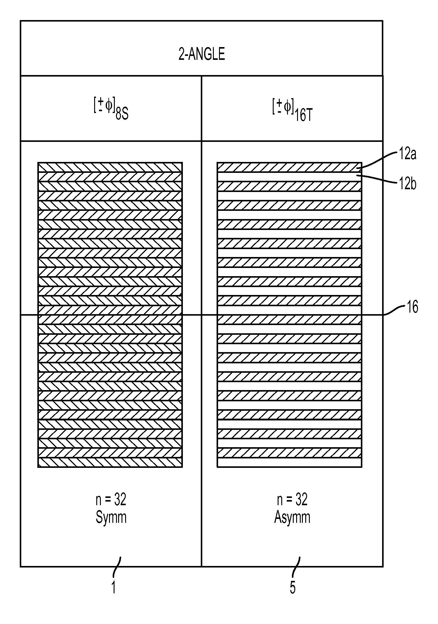
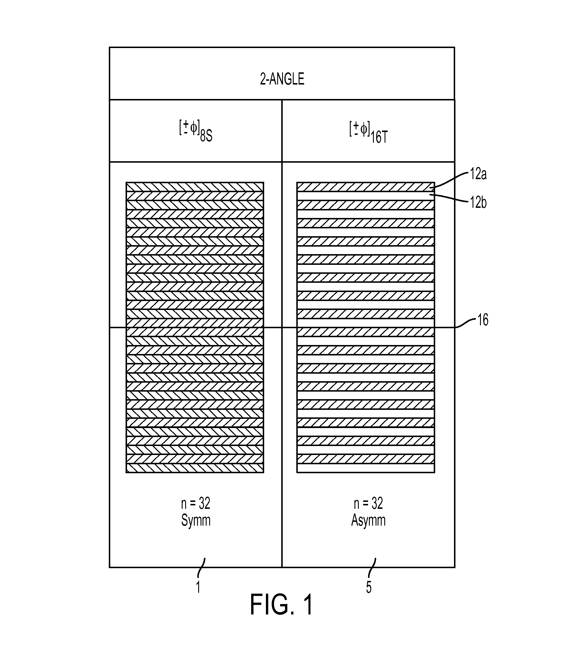
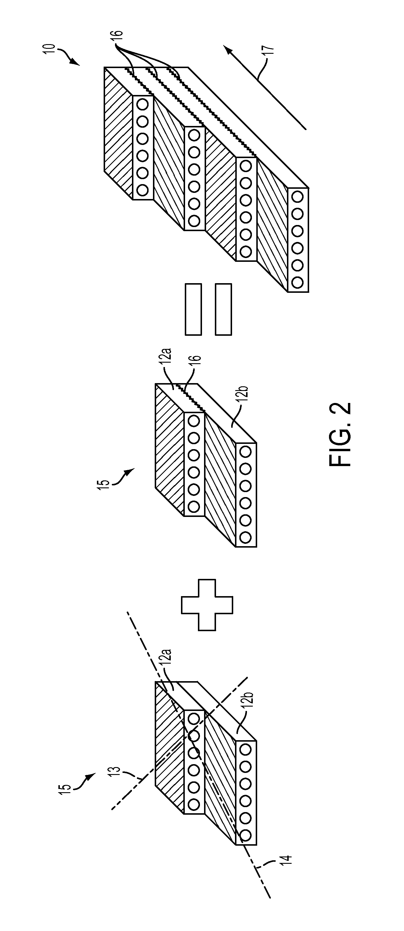
[0012]Briefly, various embodiments of the present invention address the above needs and achieve other advantages by providing a composite laminate tape comprising innovative bi-angle and thin-ply orientations, at least some of which may be further pliable relative to complex three-dimensional surfaces, so as to achieve desirable improved physical properties, facilitate more efficient and accurate manufacturing processes, and provide various products that are less costly to use and even provide improved benefits relative to conventional configurations, as described herein. Indeed, instead of using unitape for automated tape laying, filament and tape winding, and fiber placement machine in a similar manner, various embodiments described herein will replace unitape with bi-angle tape made of thin plies, and variable angles, stitched or otherwise bonded together by a unique NCF process, which altogether results in composite laminate structures having the non-limiting advantages of higher performance, higher quality, less weight, and reduced cost—relative to conventional unitape configurations.

Problems solved by technology

These constraints, in particular, have traditionally remained unchallenged due to concerns that, absence such symmetry and balance, conventionally formed structures will undesirably warp upon post-cure cool down and / or be unduly susceptible to bending or twisting upon imposition of a load force.
Unfortunately, the resulting complex stacking procedures are prone to error, resulting in excessive waste and cost, particularly where tapering of the thickness of a composite laminate structure is desirable.
Notably, such lay-up procedures are likewise time- and labor-intensive, requiring sequential rotation and orientation of each respective layer therein prior to consolidation.
In view of the above constraints, conventional laminate materials have historically created difficulty when trying to further minimize laminate thickness, which is of particular concern in those industries such as the aircraft industry, which continually seeks ever-increasingly lightweight structures.
However industry standards in the art have generally advised against relatively thin ply configurations, not only because of the inherent difficulty in even forming such, but also due to a belief that thinner plies would adversely impact material characteristics such as strength, stiffness, and the like.
Still further, key players in industries using composite laminate materials have historically perceived thin ply configurations as increasing costs, due at least in part to the notion that additional layups would be necessary to obtain a laminate structure with material characteristics comparable to the conventional four-ply balanced and symmetrical compositions.
In addition, applications involving the use of composite laminate tapes for winding or laying up complex three-dimensional surfaces have historically posed particular difficulties.
In recent years fiber placement machines have emerged to reduce these manufacturing imperfections but the extra cost of the machine and its slow layup rate have prevented wide usage.
Such either adds further weight to the structures, perhaps even unnecessarily due to the introduced uncertainties from buckling and / or wrinkling, or requires multiple seams between adjacent portions of the wrapped structures, which themselves may similarly impact strength, stiffness, and still other parameters.

Method used


Image

  • Composite bi-angle and thin-ply laminate tapes and methods for manufacturing and using the same
  • Composite bi-angle and thin-ply laminate tapes and methods for manufacturing and using the same
  • Composite bi-angle and thin-ply laminate tapes and methods for manufacturing and using the same

Examples


Embodiment Construction

[0042]Various embodiments of the present invention now will be described more fully hereinafter with reference to the accompanying drawings, in which some, but not all embodiments of the invention are shown. Indeed, embodiments of the invention may be embodied in many different forms and should not be construed as limited to the embodiments set forth herein. Rather, these embodiments are provided so that this disclosure will satisfy applicable legal requirements. The term “or” is used herein in both the alternative and conjunctive sense, unless otherwise indicated. Like numbers refer to like elements throughout.

[0043]General Foundation and Overview

[0044]In general, various embodiments of the present invention dispense with one or more of the various traditionally accepted constraints that govern laminate structure and the methods of making the same. Such constraints, as will be shown, often compromise the flexibility and benefits of structures formed therefrom Typical constraints in...


PUM

PropertyMeasurementUnit
angleaaaaaaaaaa
angleaaaaaaaaaa
angleaaaaaaaaaa

Abstract

Various embodiments provide a bi-angle pliable tape for use in forming a composite laminate structure. The bi-angle pliable tape comprises: a longitudinal axis extending in a unidirectional machine direction; a first ply comprising fibers extending in a first orientation, the first orientation being offset relative to the longitudinal axis at a first angle of less than 30°; and a second ply comprising fibers extending in a second orientation, the second orientation being opposite the first orientation relative to the unidirectional machine direction. The first ply and the second ply are further secured substantially adjacently relative to one another by one or more yarns so as to provide a non-crimped configuration such that the bi-angle tape defines a pliable structure. Corresponding composite laminate structures and methods for making the same are provided. Composite laminate integrated bulkheads, containment rings, and penetration resistant articles and corresponding methods of making the same are provided.

Description

THE NAMES OF THE PARTIES TO A JOINT RESEARCH AGREEMENT[0001]A joint research agreement was executed and rendered effective on Jul. 6, 2012 for the development of technology related to composite laminate structures and / or methods for manufacturing and using the same. The names of the parties executing the joint research agreement are The Board of Trustees of the Leland Stanford Junior University and Chomarat, also known as Compagnie Chomarat.BACKGROUND[0002]1. Field of Invention[0003]The present invention relates generally to composite laminate tapes, in particular those containing shallow bi-angle and thin-ply orientations to achieve desirable improved physical properties, together with methods for manufacturing and using such tapes.[0004]2. Description of Related Art[0005]Conventional composite laminate materials are generally designed to emulate the strength characteristics of conventional metal-based structural materials, and as such have been typically constrained to designs hav...

Claims


Application Information

Patent Timeline
Patent Type & Authority Applications(United States)
IPC IPC(8): B32B5/12B32B5/26B32B38/18
CPCB32B5/12B32B38/1816B32B5/26B32B2305/00B32B2250/03B32B2250/40B32B2250/05B32B2309/06B32B2307/52B32B2307/54B32B2307/558B32B5/06B32B2405/00B32B2571/00B29C70/202Y10T428/24099Y10T428/24116Y10T156/10
Inventor TSAI, STEPHEN W.COGNET, MICHELSANIAL, PHILIPPE
Owner THE BOARD OF TRUSTEES OF THE LELAND STANFORD JUNIOR UNIV
Why Eureka
Try Eureka