
Adjustable bicycle fender assembly

a fender assembly and adjustable technology, applied in the field of bicycles, can solve the problems of bicycles, bicycles, rider's clothes, wet surfaces being particularly problematic with tire spray, etc., and achieve the effect of reducing the risk of slipping, and reducing the safety of cyclists

Active Publication Date: 2012-05-08
TREK BICYCLE CORPORATION
View PDF51 Cites 17 Cited by
  • Summary
  • Abstract
  • Description
  • Claims
  • Application Information

AI Technical Summary

Benefits of technology

The system allows for convenient and precise adjustment of the fender's orientation relative to the bicycle wheel, reducing the need for multiple operators and minimizing hardware waste, while maintaining effective debris deflection without snagging issues.

Problems solved by technology

Wet surfaces are known to be particularly problematic with respect to tire spray.
The dirt and water propelled by operation of the bicycle wheels has a tendency to soil the bicycle, the rider, and the rider's clothes.
Although many bicycle fender systems are known, such systems are not without their respective drawbacks.
Many known fender systems are simply non-adjustable requiring the user to locate a fender system designed for their particular bicycle.
Such systems create undue expenses on manufacturers in as much as such systems requiring a wide array of product offerings that vary by fender shape and connection modalities which correspond to only limit configurations of underlying bicycles.
Such systems are less than desirably environmental conscious in that the end user then simply discards extra mounting hardware that is inapplicable to the mounting of the fender to the bicycle of the given user.
Although such systems can be configured to provide a desired orientation of the fender relative to the underlying tire by a single operator, such manipulation is commonly time consuming as well as frustrating.
Unfortunately, the fairly fixed orientation of the fender assembly prior to connecting the same to the bicycle often achieves a less than desired positioning and orientation of the fender when the assembly is connected to the bicycle.
Such systems also commonly suffer from another drawback.
Although these extensions are necessary to facilitate the cooperation of the fender assembly with a number of bicycle constructions, they can also undesirably snag or piece materials or structures that pass in close proximity to the fender.

Method used


Image

  • Adjustable bicycle fender assembly
  • Adjustable bicycle fender assembly
  • Adjustable bicycle fender assembly

Examples


Embodiment Construction

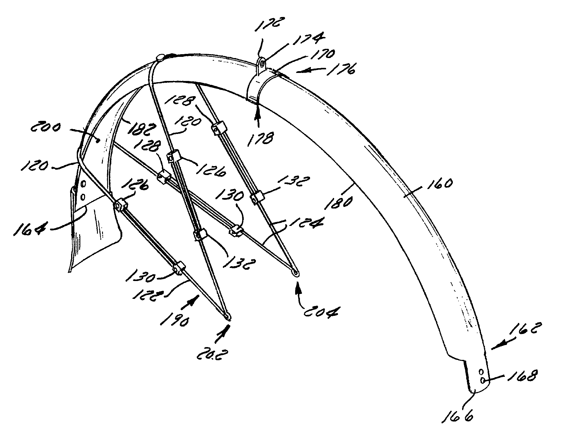
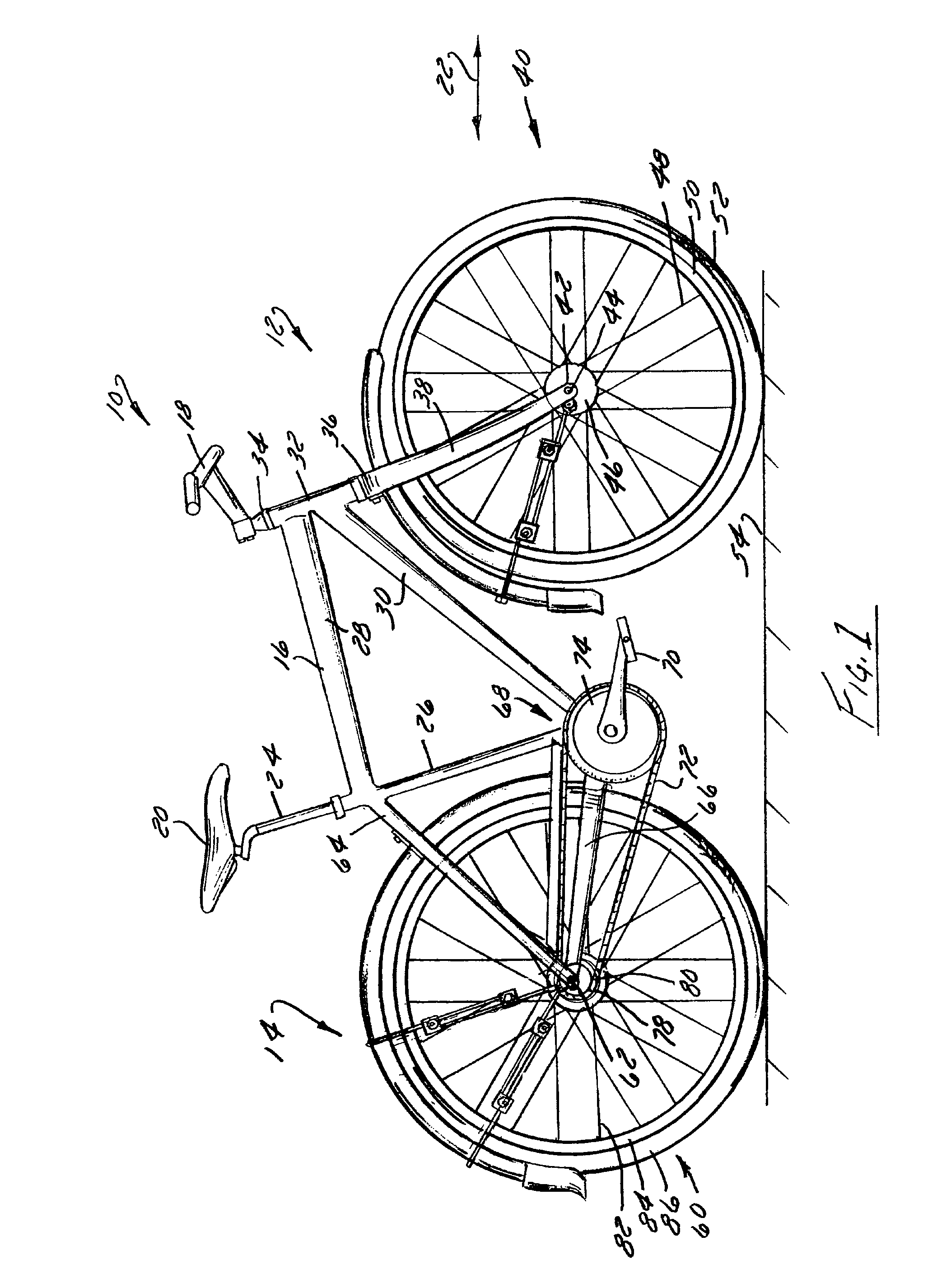
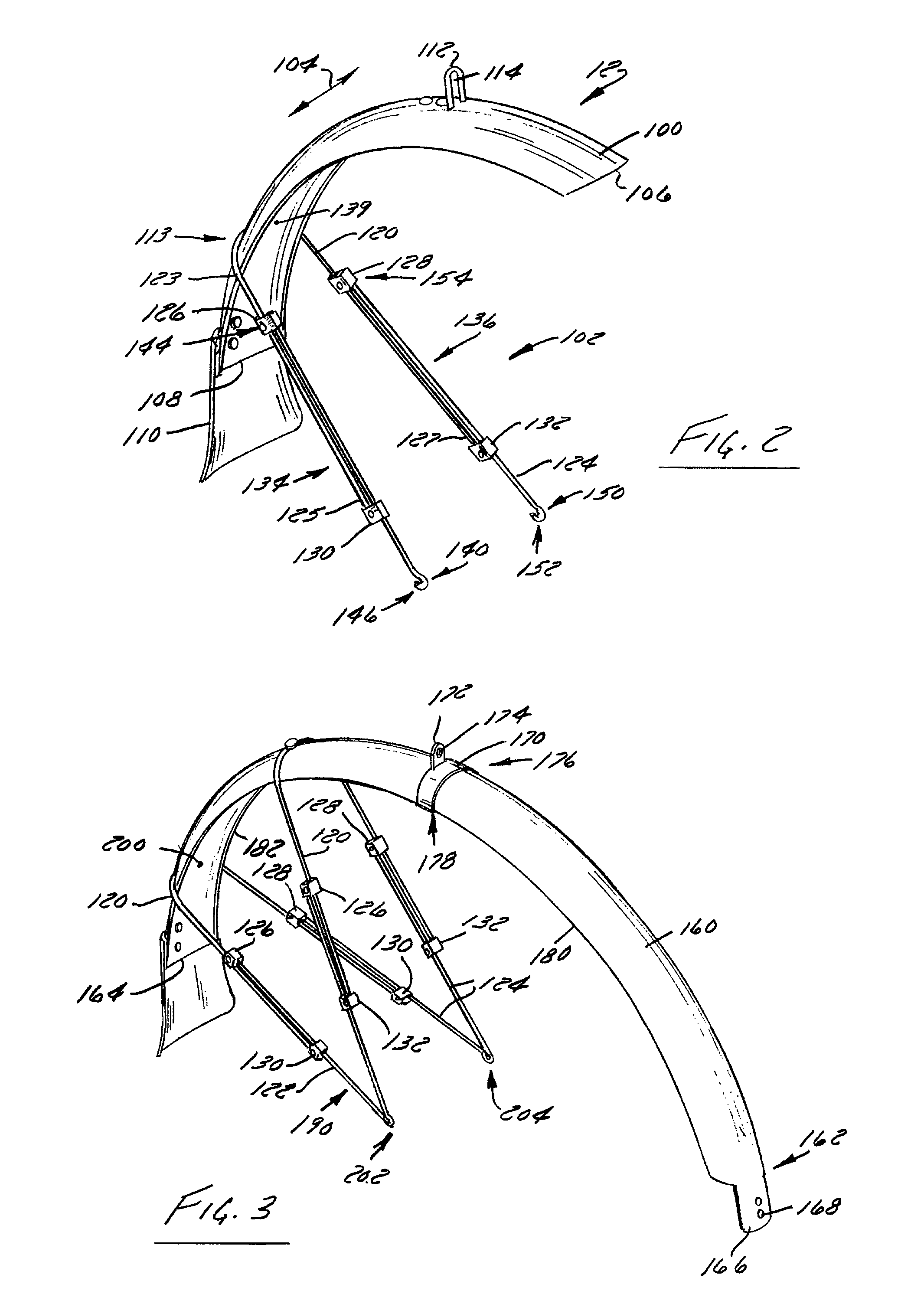
[0025]FIG. 1 shows a bicycle 10 equipped with a forward fender assembly 12 and a rear fender assembly 14 according to the present invention. Fender assemblies 12, 14 are attached at a number of locations to a frame 16 or other non-moving structures of bicycle 10, such as the stays. Bicycle 10 includes handlebars 18 that are attached to frame 16 generally forward of a seat 20 relative to a longitudinal axis, indicated by arrow 22, of bicycle 10. A seat post 24 extends in a downward direction from seat 20 and slidably or telescopically engages a seat tube 26 of frame 16. Frame 16 includes a top tube 28 and a down tube 30 that extend forward from seat tube 26 to a head tube 32 that connects the generally forward ends of top tube 28 and down tube 30.

[0026]Handlebars 18 are connected to a stem 34 that passes through head tube 32 of frame 16. Stem 34 is secured to a fork crown 36. A pair of forks 38 extend from generally opposite lateral ends of fork crown 36 and support a front wheel ass...


PUM

PropertyMeasurementUnit
lengthaaaaaaaaaa
overlap lengthaaaaaaaaaa
shapeaaaaaaaaaa

Abstract

A fender mounting system that is particularly applicable to bicycles and that includes one or more adjustable strap assemblies that connect the fender to the bicycle. The strap assemblies include a first portion that is individually securable to the fender and a second portion that is individually securable to the underlying bicycle. A clamp assembly cooperates with the respective portions of the strap assembly so that the portions of the strap assembly bypass one another when the clamp assembly is loose to allow positioning of the fender relative to the wheel while the fender assembly is attached, albeit loosely, to the bicycle. Tightening of the clamp assembly fixes the position of the fender relative to an adjacent wheel.

Description

BACKGROUND OF THE INVENTION[0001]The present invention relates generally to bicycles and, more particularly, to a fender assembly whose orientation can be adjusted relative to the underlying bicycle so as to maintain a generally concentric orientation of the fender with respect to an adjacent wheel.[0002]With the every increasing popularity of bicycle riding, whether for fitness, recreation, or transportation, there is ever present pressure for the providing of bicycles that can be operated during periods of less than desirable riding conditions. Many riders are familiar with the undesirable effects of tire spray. Commonly, when a bicycle is riding over wet or dirty surfaces, debris accumulated through the interaction of the tire with the road or ground is propelled in radially outward directions from the tire as the tires rotate over the operating surface. Wet surfaces are known to be particularly problematic with respect to tire spray. The dirt and water propelled by operation of ...

Claims


Application Information

Patent Timeline
Patent Type & Authority Patents(United States)
IPC IPC(8): B62D25/18
CPCB62J15/02Y10T29/49895
Inventor BYBEE, ERIC
Owner TREK BICYCLE CORPORATION
Learn More