

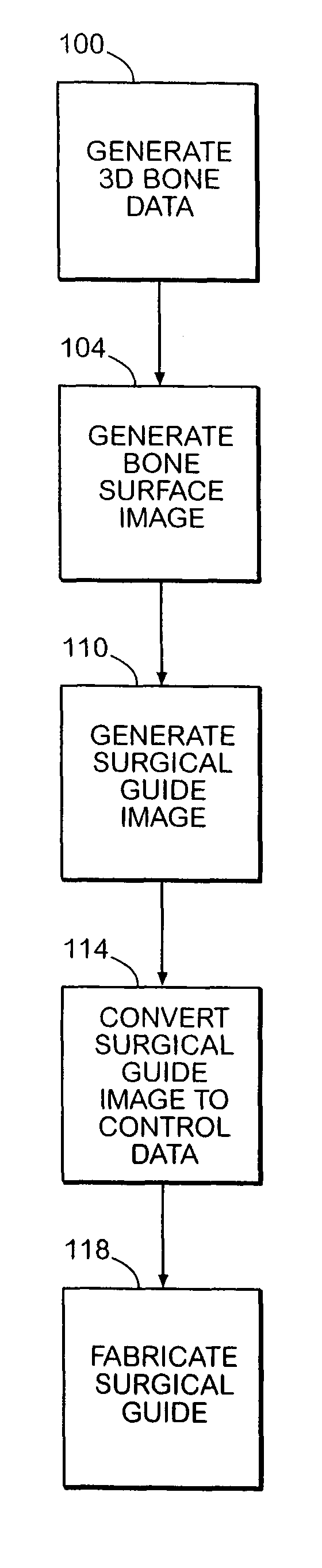
System and method of designing and manufacturing customized instrumentation for accurate implantation of prosthesis by utilizing computed tomography data
a computed tomography and customized instrument technology, applied in the field of customized instruments, can solve the problems of acetabular cup not fully sitting in the reamed cavity of the acetabulum, surgeons may have difficulty in reaming a properly sized cavity, and the sub-hemispherical configuration suffers from a number of limitations, so as to achieve quick and accurate implantation of the guide, easy oriented, and quick fabrication
- Summary
- Abstract
- Description
- Claims
- Application Information
AI Technical Summary
Benefits of technology
Problems solved by technology
Method used
Image

Examples
Embodiment Construction
[0035]For the purposes of promoting an understanding of the principles of the invention, reference will now be made to the environment and embodiments of the invention illustrated in the drawings and described in the following written specification. No limitation to the scope of the invention is thereby intended. The present invention includes any alterations and modifications to the illustrated embodiments and includes further applications of the principles of the invention as would normally occur to one skilled in the art to which this invention pertains.
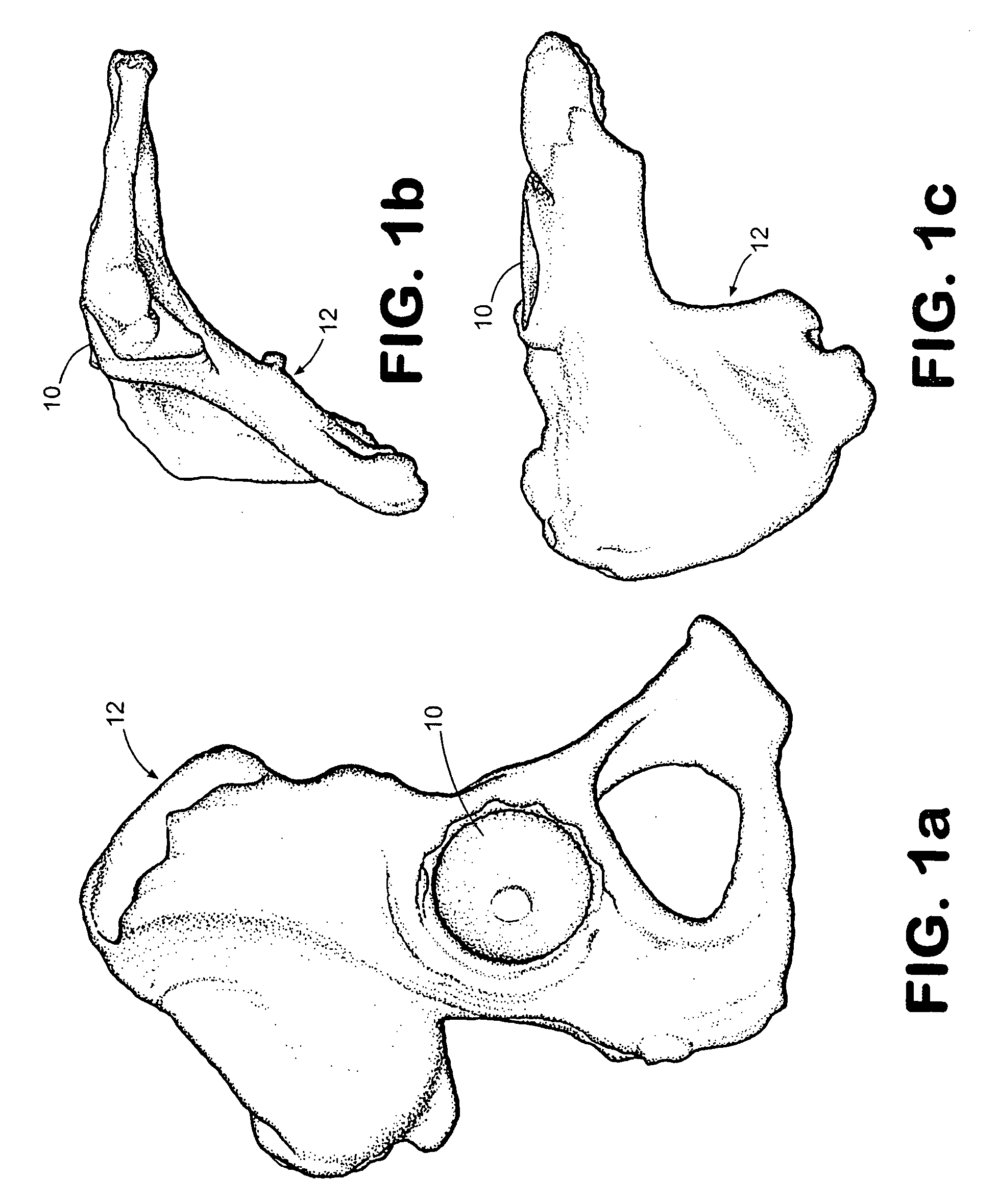
[0036]In order to perform the method of the present invention, bone anatomical data is required. One way of obtaining this bone anatomical data is to perform a CT series on the patient in the area to be reconstructed. For a hip replacement, the patient is preferably scanned from the superior rim of the pelvis to the most inferior portion of the ischium in approximately 3 mm slices. Larger slices may not provide the detail in bone ...
PUM
 Abstract
Description
Claims
Application Information