
Vibrating micro-mechanical sensor of angular velocity

a micro-mechanical sensor and vibration technology, applied in the direction of acceleration measurement using interia force, turn-sensitive devices, instruments, etc., can solve the problems of difficult measurement in several degrees of freedom, cost effective implementation, and extremely tight requirements, and achieve reliable measurement, cost-effective, and good performance.

Active Publication Date: 2012-05-15
MURATA MFG CO LTD
View PDF14 Cites 32 Cited by
  • Summary
  • Abstract
  • Description
  • Claims
  • Application Information

AI Technical Summary

Benefits of technology

[0020]The object of the invention is to provide such an improved vibrating sensor of angular velocity, which enables reliable measuring with good performance in two or three degrees of freedom, particularly in solutions of small vibrating sensors of angular velocity, which in comparison with prior art solutions is remarkably cost efficient and, at the same time, can be designed to be insensitive to coupling of external mechanical interference.

Problems solved by technology

Particularly in demanding applications, such as e.g. driving control systems in the car industry, these requirements are extremely tight.
Measuring in several degrees of freedom is challenging in sensors of angular velocity, since often both activation and detection in more than one degree of freedom are required.
In particular, a cost effective implementation in one component for measuring angular velocity in relation to an axis in the surface plane and in relation to an axis perpendicular to the plane, has proved to be a challenge.
Cost effectiveness in sensors of angular velocity is determined, in addition to the surface area, also by the complexity of the electronics required for the element.
The activation motion occurring in several degrees of freedom in the measuring resonators for different axes is perhaps the biggest single factor increasing the surface area and the complexity of the electronics.

Method used


Image

  • Vibrating micro-mechanical sensor of angular velocity
  • Vibrating micro-mechanical sensor of angular velocity
  • Vibrating micro-mechanical sensor of angular velocity

Examples


Embodiment Construction

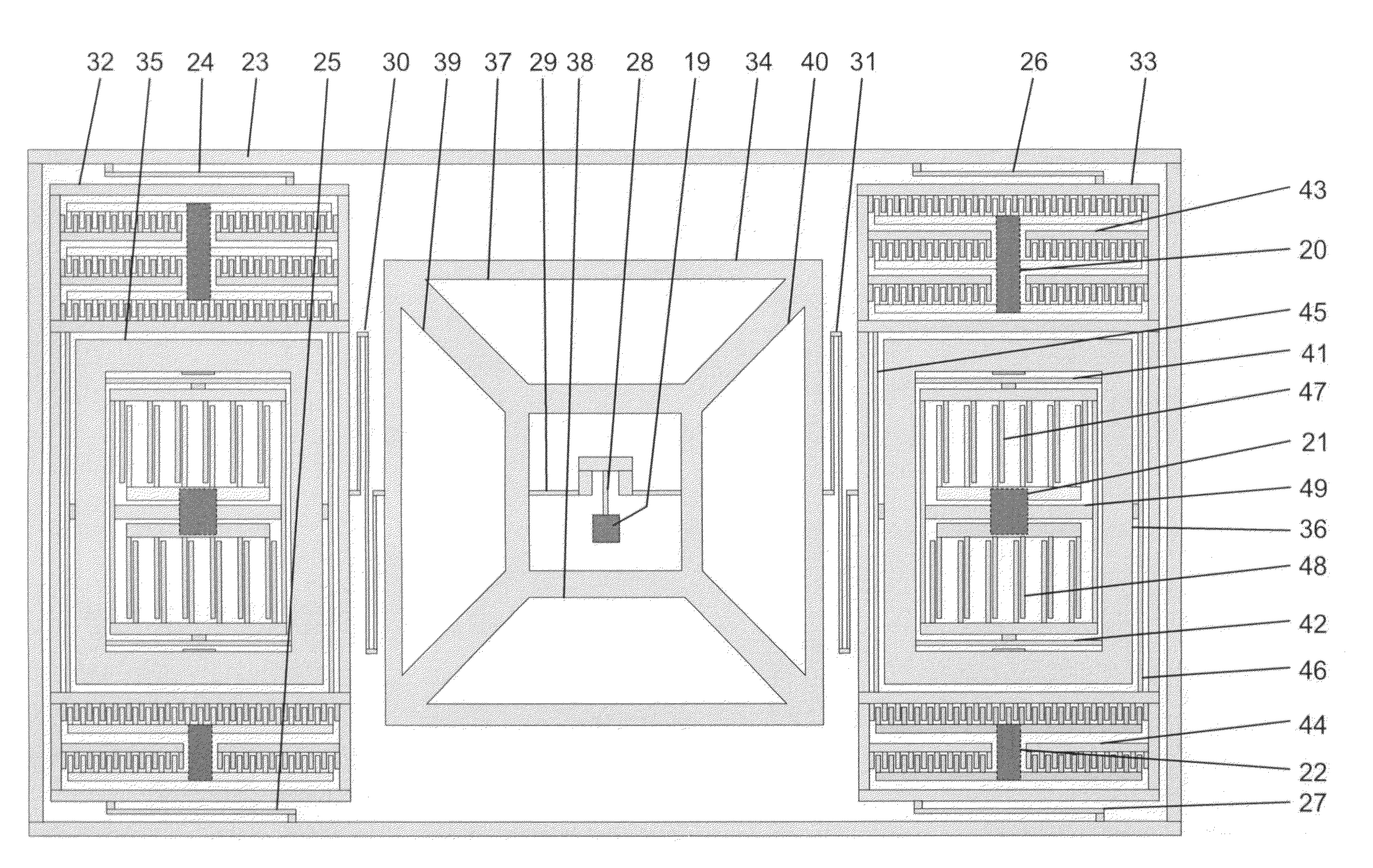
[0037]FIG. 4 shows a diagram of the functional structure of a vibrating micro-mechanical sensor of angular velocity with three axes according to the invention. The depicted vibrating micro-mechanical sensor of angular velocity with three axes according to the invention comprises a rotation mass 34, which is supported at the center to a support structure 19 by means of springs 28, 29 and supported in the X axis direction to excitation frame structures 32, 33 by means of springs 30, 31. The rotation mass 34 further comprises electrodes 37-40. Additionally, the vibrating micro-mechanical sensor of angular velocity with three axes according to the invention comprises linear masses 35, 36, which are supported in the X axis direction to the excitation frame structures 32, 33 by means of springs 45, 46. Said excitation frame structures 32, 33 are supported in the Y axis direction to a frame 23 around the edge of the sensor by means of bending springs 24-27. Additionally, the vibrating micr...


PUM


Abstract

Embodiments of the invention relate to measuring devices used in measuring angular velocity and, more precisely, to vibrating micro-mechanical sensors of angular velocity. The sensor of angular velocity according to an embodiment of the invention is adapted to measure angular velocity in relation to two or three axes, and at the least two seismic masses (34-36, 52-53, 71-75) of the sensor of angular velocity are adapted to be activated into primary motion vibration by a common mode. The structure of the sensor of angular velocity according to the invention enables reliable measuring with good performance, particularly in small size vibrating micro-mechanical sensors of angular velocity.

Description

FIELD OF THE INVENTION[0001]The invention relates to measuring devices used in measuring angular velocity and, more precisely, to vibrating micro-mechanical sensors of angular velocity. The object of the invention is to provide an improved sensor structure enabling reliable measuring with two or three degrees of freedom and with good performance, particularly in small vibrating micro-mechanical solutions for a sensor of angular velocity.BACKGROUND OF THE INVENTION[0002]Measuring based on a vibrating sensor of angular velocity has proved to be a method of measuring angular velocity having a simple concept and being reliable. The principle of operation of vibrating sensors of angular velocity most often used is the so called tuning fork principle.[0003]In a vibrating sensor of angular velocity, a certain known primary motion is produced and it is maintained in the sensor. The motion to be measured by means of the sensor is then detected as a deviation of the primary motion. In the tun...

Claims


Application Information

Patent Timeline
Patent Type & Authority Patents(United States)
IPC IPC(8): G01P3/00G01C19/56
CPCG01C19/5712G01C19/5762G01C19/5747
Inventor BLOMQVIST, ANSSI
Owner MURATA MFG CO LTD
Learn More