Subsurface deployable antenna array

a technology of deployable antenna array and subsurface, which is applied in the direction of insulated conductors, special purpose vessels, cables, etc., can solve the problems of limiting the bandwidth of transmitted signals, unable to remain undetected and communicate at depth and speed, and extremely low data rates

Inactive Publication Date: 2012-05-15
THE UNITED STATES OF AMERICA AS REPRESENTED BY THE SECRETARY OF THE NAVY
View PDF15 Cites 13 Cited by
  • Summary
  • Abstract
  • Description
  • Claims
  • Application Information

AI Technical Summary

Benefits of technology

[0029]It is a still further object of the present invention to provide an antenna array which can be compactly stowed.
[0030]It is a still further object of the present invention is to provide an antenna array that can be automatically retrieved, compacted and stowed at termination of deployment while at cruising speed and depth.

Problems solved by technology

It is a challenge for undersea vehicles to maintain broadband communications via satellite links and with surface vessels while remaining undetected at cruising speed and depth.
Therefore, without an external antenna, an undersea vehicle cannot remain undetected and communicate at depth and speed.
Seawater skin depths at these frequencies permit communications to some significant depth, but the long wavelengths limit the bandwidth of the transmitted signal.
Consequently data rates are extremely low.
This low data rate can make it difficult or impossible to transmit lengthy messages or images.
However, at shallow depths, the undersea vehicle is easily detectable and vulnerable.
However, the relatively small and low profile antennas are susceptible to washover.
In the prior art, these multiple antenna arrays require substantial storage space when not deployed.
The problem is that undersea vehicles have very limited available storage space.
The above-cited prior art does not adequately disclose a low-profile, undersea antenna array implementation that is stored in a retracted (or physically compressed) state while stowed in a limited storage space, but upon deployment, expands to a full operational dimension.

Method used


Image

  • Subsurface deployable antenna array
  • Subsurface deployable antenna array
  • Subsurface deployable antenna array

Examples


Embodiment Construction

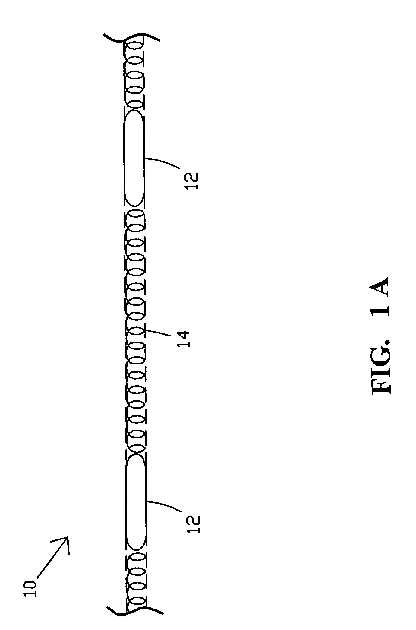
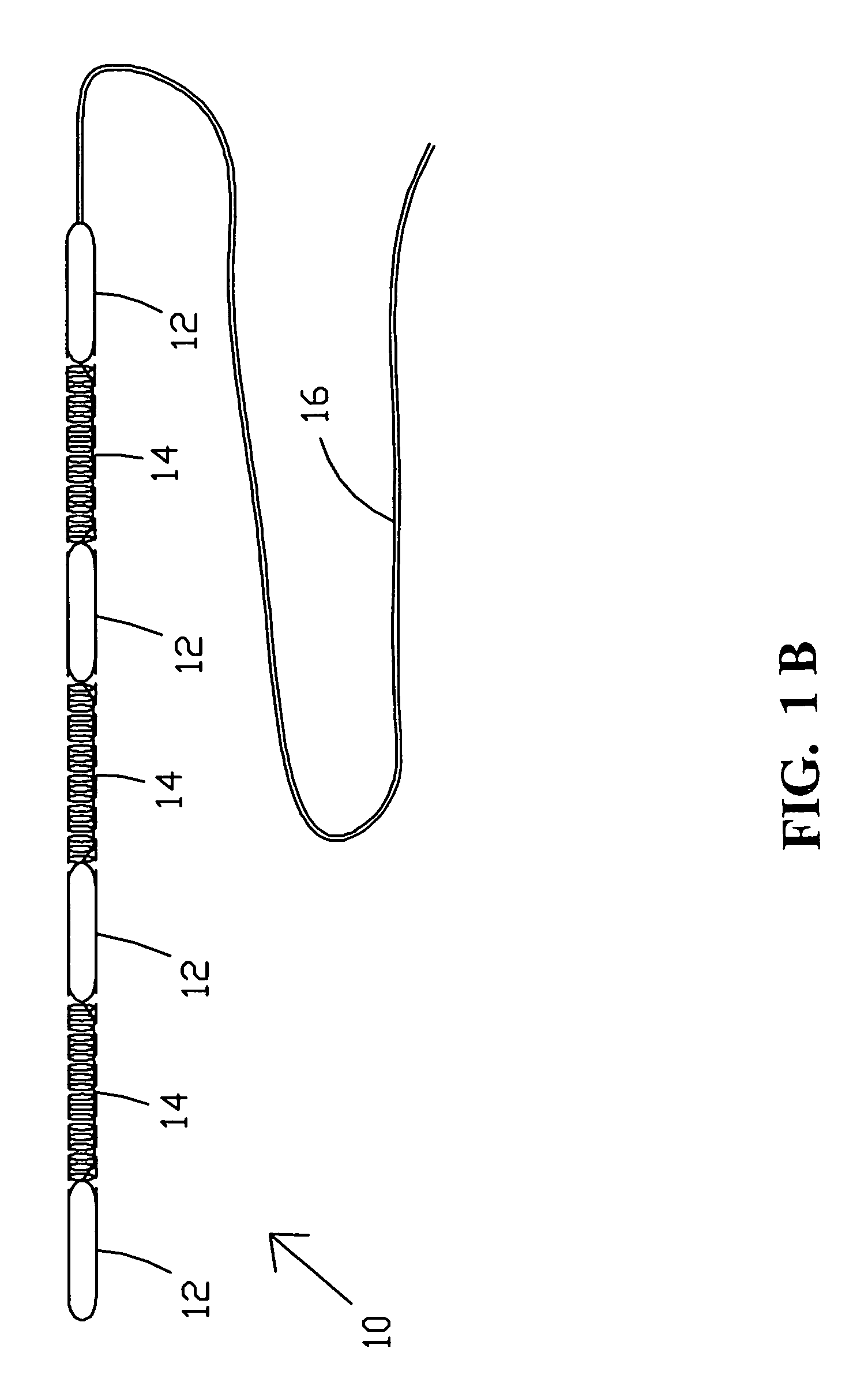
[0046]Referring now to the drawings, and more particularly to FIG. 1A, FIG. 1B, and FIG. 2, there is shown one embodiment of antenna array 10. The antenna array 10 comprises a plurality of antenna modules 12 which may vary in number. Each antenna module 12 may comprise one or more antenna elements, which may be configured in a wide variety of different ways.

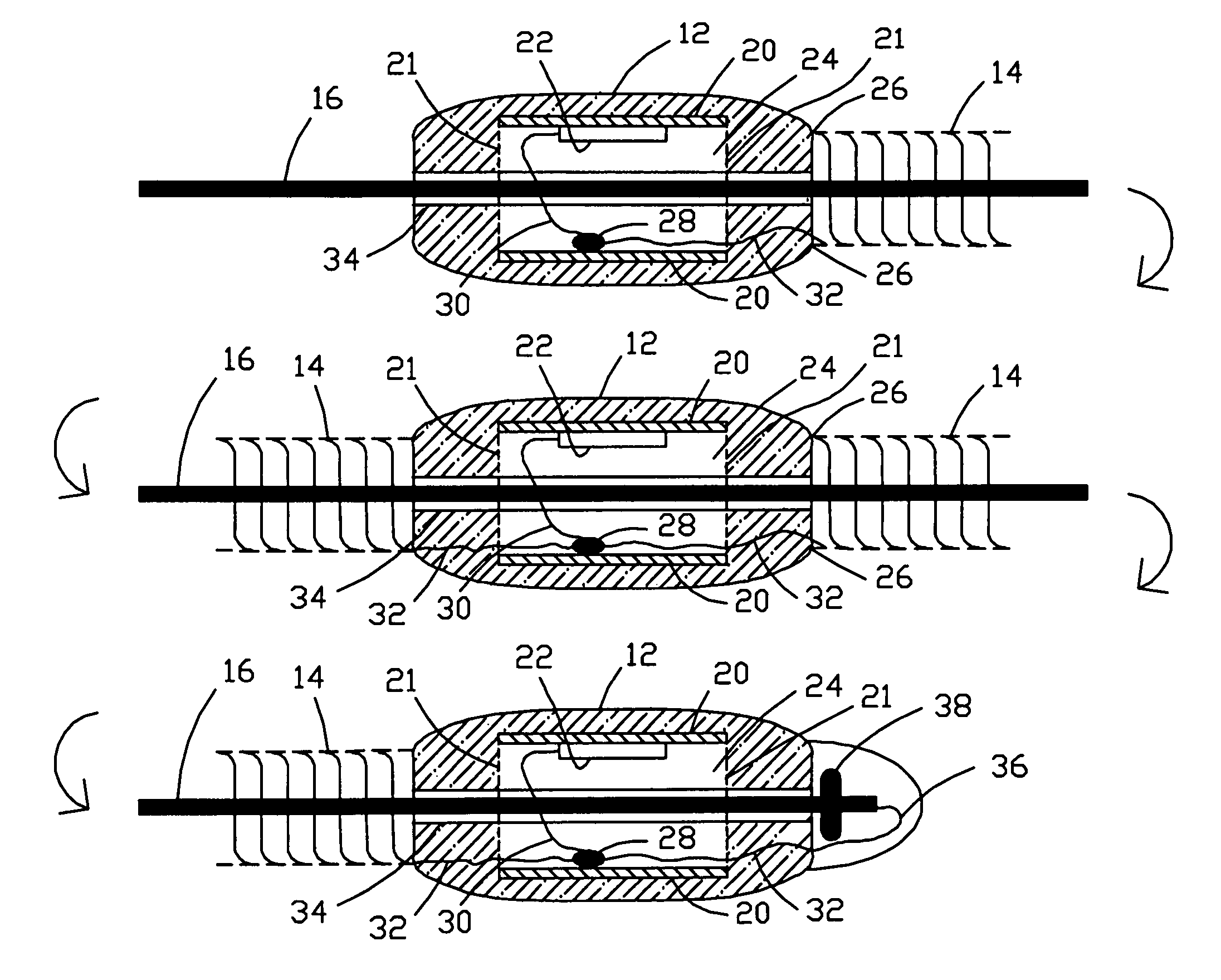
[0047]Disposed between the antenna modules 12 are expandable / contractable connectors 14. The spacing between the antenna modules 12 is determined by the state of the expandable / contractable connectors 14. In FIG. 1A, the connectors 14 are shown in an expanded state thereby increasing the spacing between the antenna modules 12. In FIG. 1B, the connectors 14 are shown in a contracted or stowable configuration.

[0048]The connectors 14 comprise metallic and / or fiber optic cables which interconnect with the antenna modules 12. The metal wiring discussed herein may typically comprise copper wiring. The metallic and / or fiber optic cables...


PUM


Abstract

A subsurface deployable antenna array is provided which expands upon deployment and contracts for storage to provide an antenna array that can be stored in a comparatively compact space. Electronically interconnected antenna modules are connected by expandable / contractable connectors. A helically-organized bundle of optical cables and electrical wiring are utilized in the expandable / contractable connectors. Mechanical, electrical, or hydraulic means may be utilized to control the spacing between the antenna modules.

Description

STATEMENT OF GOVERNMENT INTEREST[0001]The invention described herein may be manufactured and used by or for the Government of the United States of America for governmental purposes without the payment of any royalties thereon or therefore.CROSS REFERENCE TO OTHER PATENT APPLICATIONS[0002]None.BACKGROUND OF THE INVENTION[0003](1) Field of the Invention[0004]The present invention relates generally to subsurface deployable antennas and, more particularly, to a cable deployed antenna array having watertight antenna elements which move away from each other for operation, and then move toward each other for compact storage.[0005](2) Description of the Prior Art[0006]It is a challenge for undersea vehicles to maintain broadband communications via satellite links and with surface vessels while remaining undetected at cruising speed and depth.[0007]The electrical conductivity of seawater inhibits electromagnetic radiation (radio signals) from penetrating to significant depths below the sea s...

Claims


Application Information

Patent Timeline
Patent Type & Authority Patents(United States)
IPC IPC(8): H01Q1/34H01Q1/16H02G11/02
CPCH01Q1/34H01Q21/08H02G9/00H01B7/045H01B7/12
Inventor CLARK, JAMES H.YANKIELUN, NORBERT E.
Owner THE UNITED STATES OF AMERICA AS REPRESENTED BY THE SECRETARY OF THE NAVY
Why Eureka
Try Eureka