End-connector and method for fastening a flat-belt type suspension means of an elevator system

a technology of end-connector and suspension means, which is applied in the direction of elevators, snap fasteners, buckles, etc., can solve the problem that the correct wrapping in the specified arrangement that produces the self-locking effect cannot be reliably deduced, and achieves the effect of convenient recognition

Inactive Publication Date: 2012-05-22
INVENTIO AG
View PDF9 Cites 11 Cited by
  • Summary
  • Abstract
  • Description
  • Claims
  • Application Information

AI Technical Summary

Benefits of technology

[0010]Extending between the two side walls are at least a first and a second wrapping element. In addition, further wrapping elements can be provided to increase the total wrapping angle of the suspension means over all wrapping elements and thereby the frictional engagement between suspension means and end-connector and / or another wrapping arrangement.
[0012]Preferably, the second wrapping element is releasably connectable with the two side walls. Installability of the suspension means in the end-connector is thereby greatly improved. This is because on the remote second wrapping element the suspension means can first be simply inserted into the end-connector. Also, after removal of the second wrapping element, the suspension means can be more easily pulled out of the end-connector.
[0022]Such integral marking has a number of advantages. Firstly, it is more resistant to the harsh environmental conditions that generally prevail in elevator hoistways than a subsequently applied marking. Furthermore, even with a soiled surface, it is still detectable, particularly haptically. Moreover, manipulations of the marking can be prevented.
[0024]Particularly preferably, the breakthrough cuts the marking that is present on the outside of the housing that symbolizes the specified arrangement of the suspension means, thereby ensuring that the suspension means with correct wrapping arrangement is visible in the breakthrough. With correct arrangement of the suspension means, as on entry of the suspension means into, or its exit from, the end-connector, also in the said breakthrough, the visible route of the suspension means through the marked route of the suspension means is continued and reversed. A faulty wrapping arrangement is therefore easily recognizable.
[0025]According to a preferred embodiment of the present invention, the end-connector can comprise a dead-end hitch for fixing the dead end—i.e. the free suspension-means end—of the suspension means. This dead-end hitch can be installed in the area of an exit opening to lead out the dead end of the suspension means out of the housing, and allows the dead end of the suspension means to be held fast in the exit opening by frictional engagement. This device also helps to ensure that the suspension means is not erroneously threaded in the wrong direction through the end-connector and around the wrapping elements. Since it is obvious to everyone that with the dead-end hitch the dead end of the suspension means is to be fixed, it is immediately recognizable when the dead end of the suspension means is routed out of the wrong exit opening.

Problems solved by technology

Nevertheless, even with such faulty wrapping arrangements, frictional forces can withstand a limited tensile load so that through—especially manual—application of a verifying tensile force on the poly V belt, the correct wrapping in the specified arrangement that produces the self-locking effect cannot be reliably deduced.

Method used


Image

  • End-connector and method for fastening a flat-belt type suspension means of an elevator system
  • End-connector and method for fastening a flat-belt type suspension means of an elevator system
  • End-connector and method for fastening a flat-belt type suspension means of an elevator system

Examples


first embodiment

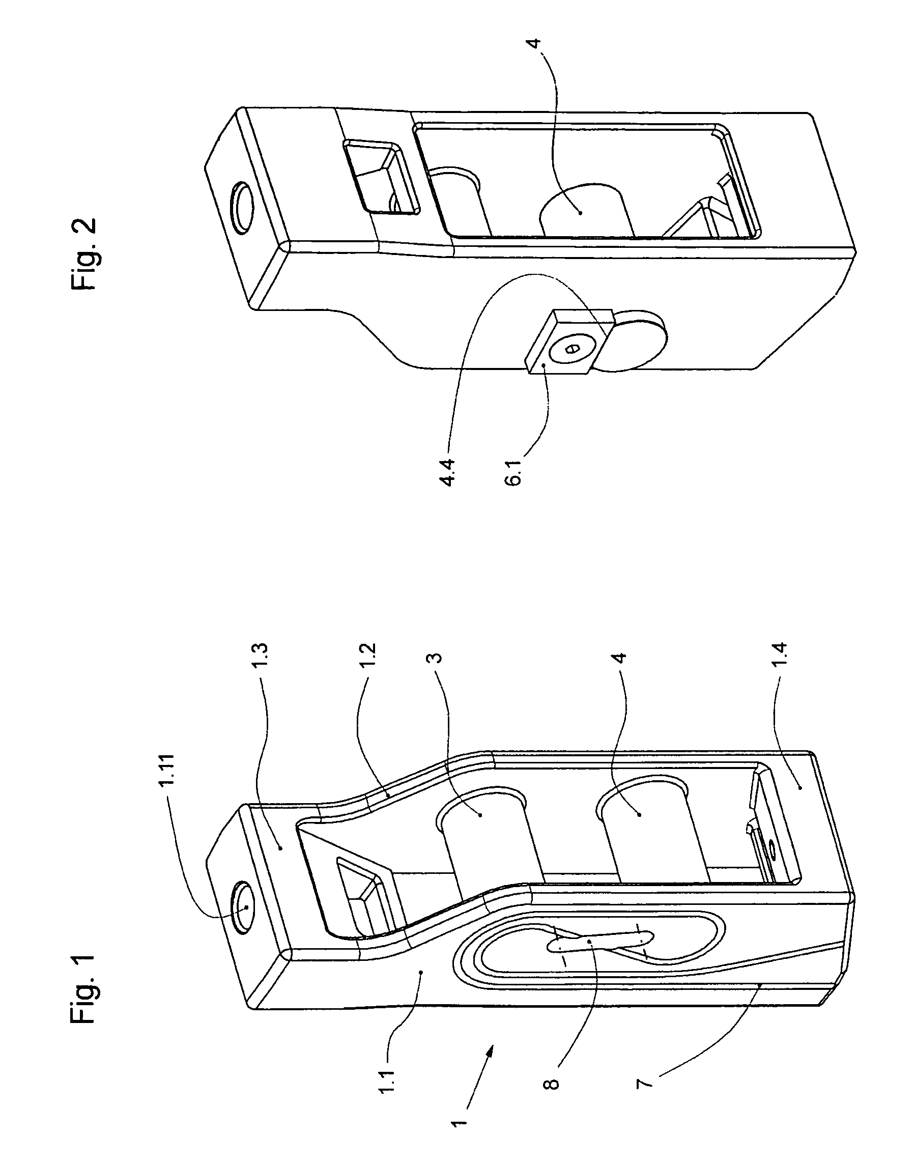
[0041]FIG. 1 shows the end-connector according to the present invention which is particularly characterized in that the wrapping elements 3, 4 that serve to fix the belt-like suspension means are permanently connected with the two side walls 1.1, 1.2 of the housing 1 of the end-connector.

second embodiment

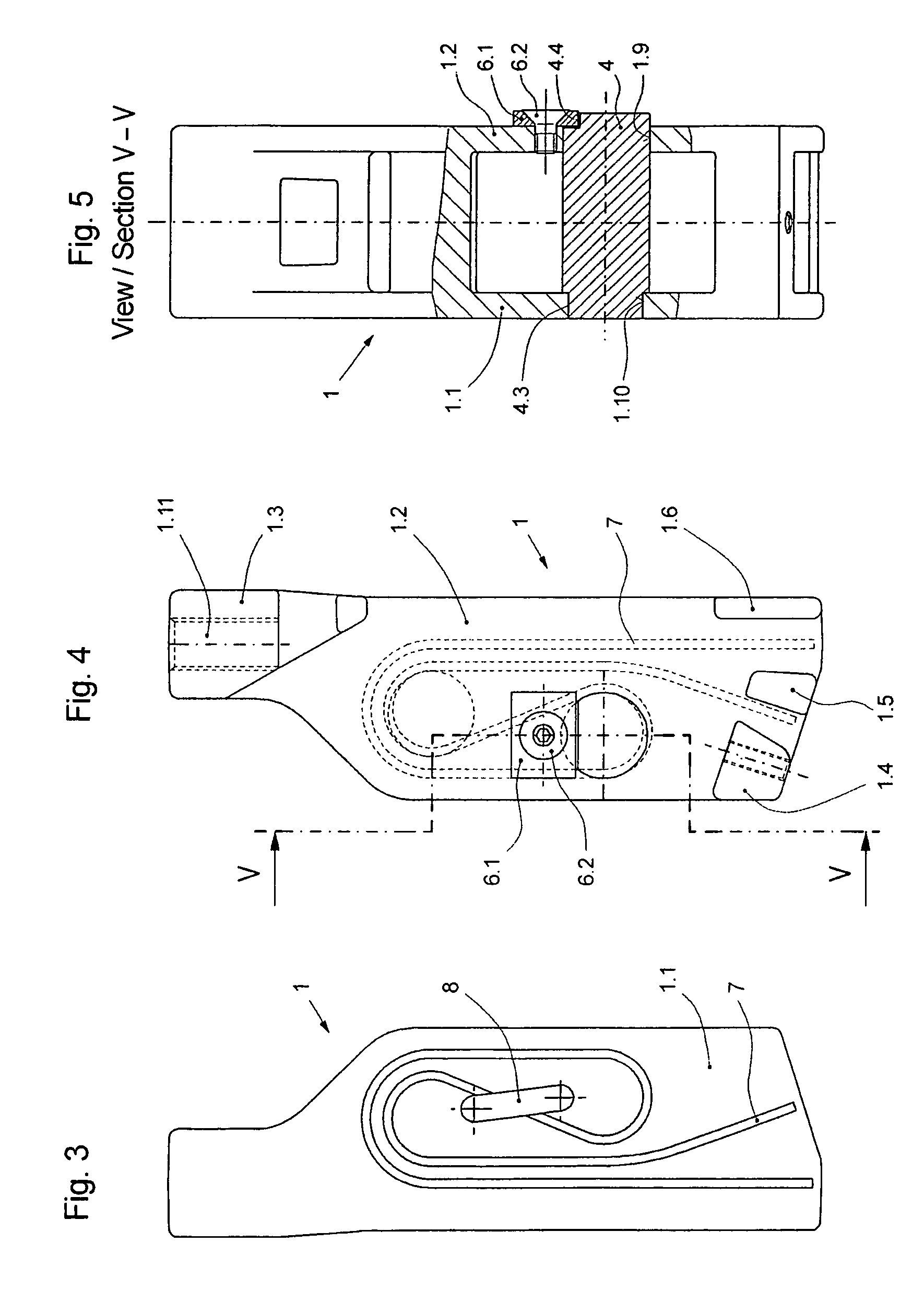
[0042]FIGS. 2, 4, and 5 show the end-connector according to the present invention, which is particularly characterized in that the second (lower) wrapping element 4 can be inserted into the two side walls 1.1, 1.2 of the housing 1 and locked in this position.

[0043]FIGS. 6 to 8 show a third embodiment of the end-connector which differs from the first and second embodiments in that the second wrapping element 4 is so executed and fixed in the housing 1 in such manner that it does not project over the side walls 1.1, 1.2.

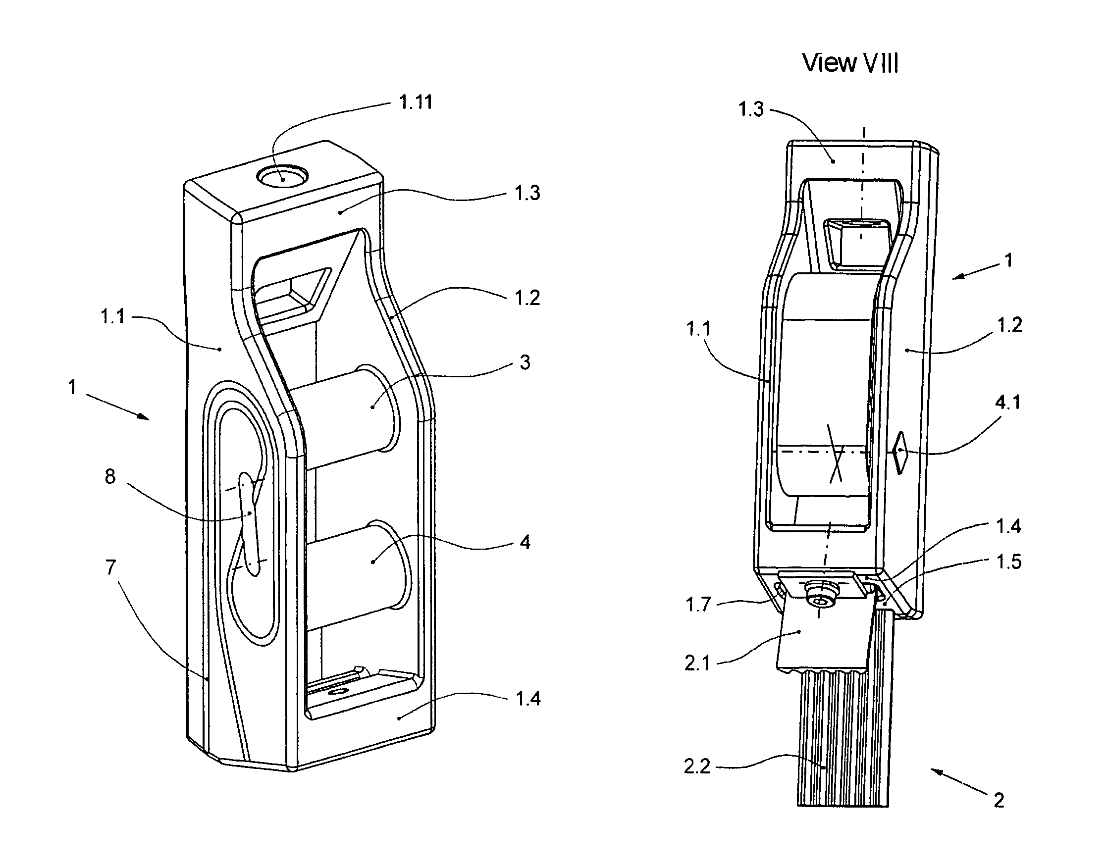
[0044]As can be particularly well seen in FIGS. 6 to 8, the housing 1 of an end-connector according to the present invention is preferably constructed as follows.

[0045]The housing comprises a first side wall 1.1 and a second side wall 1.2, which are connected by an upper yoke 1.3, and three lower yokes 1.4 to 1.6, and is manufactured monolithically as a formed part. Formed between a first lower yoke 1.4 and a second lower yoke 1.5 is an exit opening 1.7, out of which a...

third embodiment

[0046]In the end-connector illustrated with FIGS. 6 to 8, a first wrapping element 3 and a second wrapping element 4 extend between the two side walls 1.1, 1.2. The first wrapping element 3 is then also manufactured integrally with the two side walls 1.1, 1.2, and the yokes 1.3 to 1.6 by primary forming. The second, lower wrapping element 4 comprises a bolt 4.1, which can be pushed into the side walls 1.1, 1.2 from outside through side breakthroughs 1.9, 1.10 in the side walls 1.1, 1.2. Before insertion of the bolt, the bush 4.2 is pushed between the two side walls 1.1, 1.2 from in front in such manner that a pass-through opening that penetrates the bush 4.2 in its longitudinal direction aligns with the breakthroughs 1.9, 1.10. The bolt 4.1 is then pushed in through the breakthroughs 1.9, 1.10, whereby it penetrates through the pass-through opening of the bush 4.2.

[0047]The bolt 4.1 has a rectangular non-rotationally symmetrical cross section. The breakthroughs 1.9, 1.10 and the pas...


PUM


Abstract

An end-connector for fastening a flat-belt type suspension device of an elevator system comprises a housing with two side walls and a first and a second wrapping element each of which extends between the two side walls and is wrappable by the flat-belt type suspension device in a specified arrangement so as to hold the suspension means fast in the end-connector by frictional engagement. Marked on at least one of the two side walls on the outside that faces away from the wrapping elements is the specified arrangement of the suspension device.

Description

CROSS-REFERENCE TO RELATED APPLICATION[0001]This application claims the benefit of U.S. provisional patent application Ser. No. 60 / 941,743 filed Jun. 4, 2007.FIELD OF THE INVENTION[0002]The present invention relates to an end-connector and a method for fastening a flat-belt type suspension means of an elevator system as well as an elevator system with such an end-connector.BACKGROUND OF THE INVENTION[0003]The present invention starts out from EP 1 760 027 A1, from which an end-connector is known comprising a housing with two side walls and a back wall. Two wrapping elements, which in the first embodiment have a circular, in the second embodiment a wedge-shaped, cross section extend between the two side walls and are wrapped by a poly V belt in a specified arrangement in which the poly V belt, starting from a load-free dead end, first partially wraps an upper wrapping element and is guided from this to the second wrapping element, and partially wraps this in the opposite direction. F...

Claims


Application Information

Patent Timeline
Patent Type & Authority Patents(United States)
IPC IPC(8): F16G11/04
CPCB66B7/085Y10T24/3969Y10T24/39
Inventor ATTINGER, ADRIANFISCHER, DANIELRISCH, DAVID
Owner INVENTIO AG
Why Eureka
Try Eureka