Clamping device, mould thereof, and method for manufacturing the same

a technology of a clamping device and a manufacturing method, which is applied in the direction of snapping fasteners, buckles, mechanical devices, etc., can solve the problems of increasing manufacturing costs, increasing manufacturing costs, and increasing endurance, so as to reduce manufacturing costs, prevent corrosion, and easy manufacture

Inactive Publication Date: 2012-05-22
CHO YOUNG KOOK
View PDF3 Cites 4 Cited by
  • Summary
  • Abstract
  • Description
  • Claims
  • Application Information

AI Technical Summary

Benefits of technology

[0010]Therefore, the present invention has been made in view of the above problems, and it is an object of the present invention to provide a high quality clamping device, which is formed as a single component by inserting a resilient body into a molding material, thereby preventing the resilient body from being corroded and enhancing endurance of the clamping device through as well as lowering manufacturing costs and enhancing the appearance thereof, a method for manufacturing the same, and a mould for the same.
[0011]In accordance with an aspect of the present invention, the above and other objects can be accomplished by the provision of a clamping device, comprising: a W-shaped metallic member to impart resilience for clamping an item; and a casing member having the metallic member embedded therein, and formed of a polymeric material through injection-molding to prevent corrosion of the metallic member while enhancing an appearance of the clamping device. At this time, the metallic member may be inserted in the casing member in an unclamped state when injection-molding the casing member.
[0015]The supporting portion, the first and second resilient portions, and the first and second extensions of the metallic member may have through-holes formed therein, respectively, to allow the molten polymeric material to be easily infiltrated therethrough.
[0020]As apparent from the above description, according to the present invention, since a metallic member for imparting resilience is embedded in a casing member through injection-molding, the clamping device of the invention can be easily manufactured as a single component, remarkably reducing manufacturing costs. Additionally, since the metallic member is embedded in the casing member, the metallic member is prevented from being corroded, whereby the clamping device has a remarkably enhanced endurance as well as a compact structure and a high quality.

Problems solved by technology

However, as described above, since the clothespin of Korean Utility Model Registration No. 0332526 comprises the pair of pinching members 10A and 10A′, and the spring 12A applying resilience to the pair of pinching members 10A and 10A′ to clamp the laundry therebetween, it has a problem in that since at least three components must be assembled to produce the clothespin, manufacturing costs are increased.
However, as in the clothespin described above, the hairpin of the disclosure also has problems in that since at least three components comprising the upper and lower plates 2B and 3B, and the spring 9B must be assembled, and since the spring 12A is formed of a metallic material, it can be corroded, it is gradually decreased in endurance.
That is, the conventional clamping device for clamping the item has problems in that, since at least three components are required to produce the clamping device, the manufacturing costs are increased, and since the spring for imparting resilience is made of the metallic material, it is gradually corroded, thereby reducing the endurance of the clamping device.

Method used


Image

  • Clamping device, mould thereof, and method for manufacturing the same
  • Clamping device, mould thereof, and method for manufacturing the same
  • Clamping device, mould thereof, and method for manufacturing the same

Examples


Embodiment Construction

[0030]Reference will now be made in detail to the embodiments of the present invention with reference to the accompanying drawings.

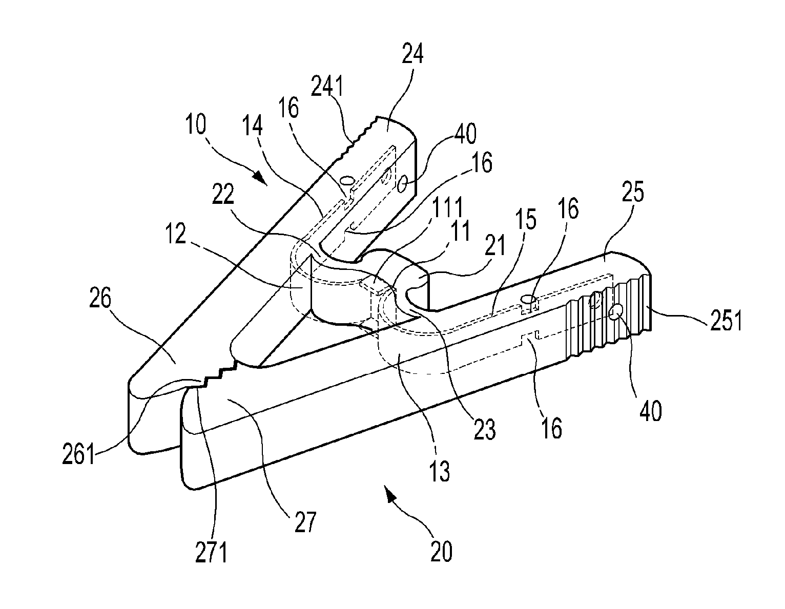
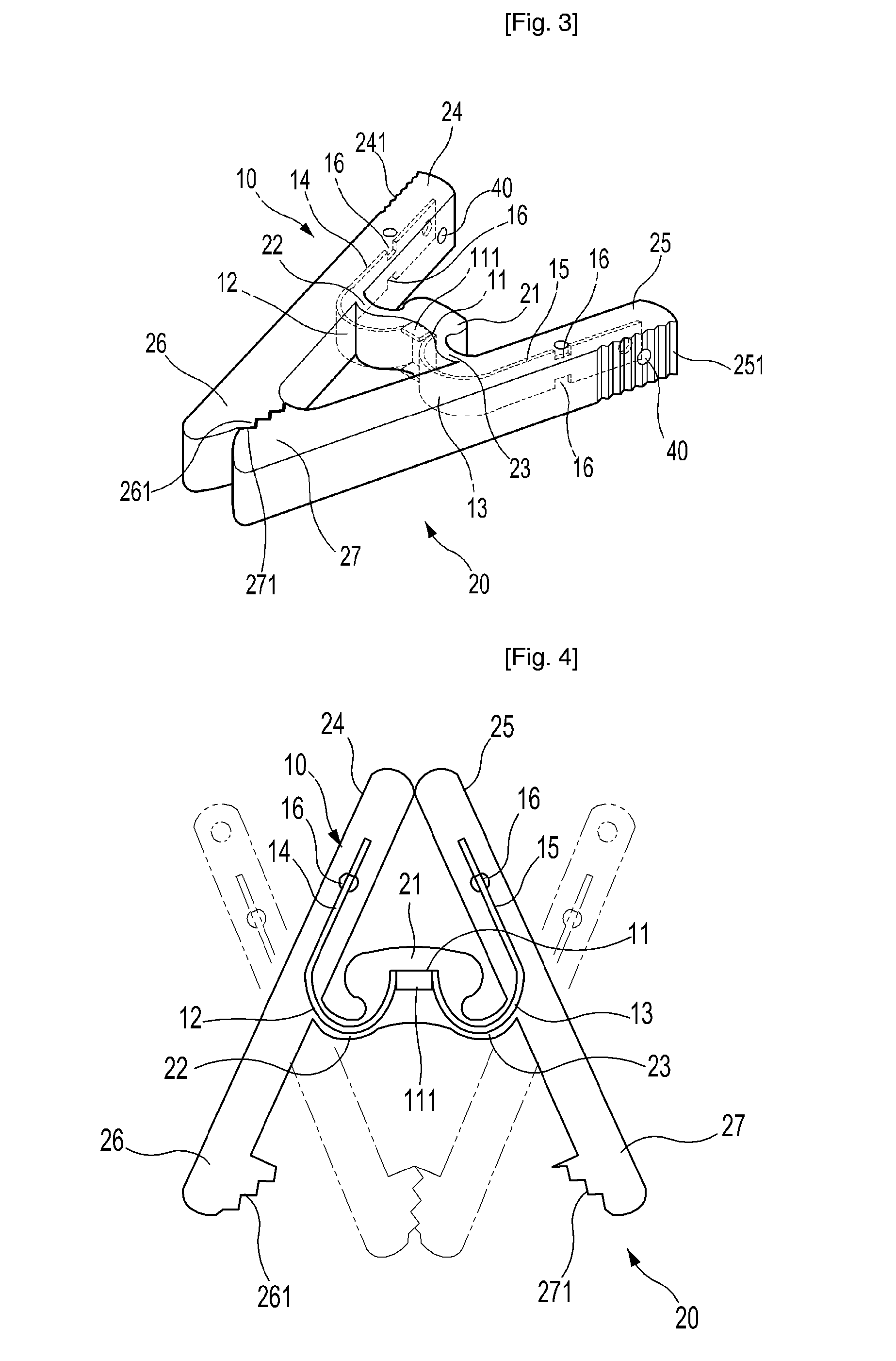
[0031]FIG. 3 is a perspective view illustrating a clamping device in accordance with a first embodiment of the present invention, FIG. 4 is an operational view illustrating clamping and unclamping states of the clamping device in accordance with the first embodiment of the invention, FIG. 5 is an operational view illustrating other clamping and unclamping states of the clamping device in accordance with the first embodiment of the invention, FIG. 6 is a perspective view illustrating a clamping device in accordance with a second embodiment of the invention, FIG. 7 is a perspective view illustrating a clamping device in accordance with a third embodiment of the invention, and FIG. 8 is a flow diagram schematically illustrating a method for manufacturing a clamping device in accordance with the invention.

[0032]Referring to FIGS. 3 to 8, reference numeral 10...


PUM

PropertyMeasurementUnit
impart resilienceaaaaaaaaaa
corrosionaaaaaaaaaa
resilienceaaaaaaaaaa

Abstract

Disclosed herein is a clamping device which can resiliency clamp an item. The claming device comprises a W-shaped metallic member to impart resilience for clamping an item, and a casing member having the metallic member embedded therein. The casing member is formed of a polymeric material through injection-molding to prevent corrosion of the metallic member while enhancing an appearance of the clamping device. A mold for the clamping device, and a method for manufacturing the same are also disclosed. Since the metallic member for imparting resilience is embedded in the casing member, the clamping device can be easily manufactured as a single component, remarkably reducing manufacturing costs. Additionally, the metallic member is prevented from being corroded, whereby the clamping device has a remarkably enhanced endurance as well as a compact structure and a high quality.

Description

FIELD OF THE INVENTION[0001]The present invention relates to a clamping device which can resiliently clamp an item (referring to a paper, hair and the like to be clamped, which will be referred to hereinafter simply as an ‘item’). More particularly, the present invention relates to a high quality clamping device, which has a compact structure to prevent corrosion of a metallic member while ensuring excellent endurance and an aesthetically pleasing appearance of the clamping device as well as easy manufacturing, a method for manufacturing the same, and a mould for the clamping device.BACKGROUND OF THE INVENTION[0002]Generally, various types of clamping devices, such as paperclips for business, hairpins for hair salon, industrial clamps, which clamp an item with resilience of a resilient body, have been suggested in various shapes. For example, Korean Utility Model Registration No. 0332526 discloses a clothespin for a laundry hanger, and Korean Utility Model Registration No. 0352859 d...

Claims


Application Information

Patent Timeline
Patent Type & Authority Patents(United States)
IPC IPC(8): F16B2/20
CPCF16B2/22Y10T24/44915Y10T24/44949Y10T24/44872Y10T24/44897Y10T29/49Y10T29/54F16B2/02D06F55/00B42F1/02A45D8/02
Inventor KIM, GYE YOUL
Owner CHO YOUNG KOOK
Why Eureka
Try Eureka