Tube system for ventilation appliances

a technology of ventilation appliances and tubes, applied in mechanical equipment, valves, respirators, etc., can solve the problem of deemed impossible to connect one tube of a single tube system to a device for a dual tube system

Active Publication Date: 2012-05-22
HAMILTON MEDICAL AG
View PDF20 Cites 35 Cited by
  • Summary
  • Abstract
  • Description
  • Claims
  • Application Information

AI Technical Summary

Benefits of technology

[0014]The leakage enables the embodiment of the ventilation tube arm with a large volume, e.g. having a large length. In this manner a single tube can be connected to the mask or to the tubus so that the patient feels as if he / she were connected to an open single tube system. The patient does not have to put up with a cumbersome exhalation valve near the patient, or with two tubes. The tube system is divided into the inhalation tube arm and the exhalation tube arm only near the appliance.
[0015]The leakage has the advantage that the patient can breathe, even if the appliance does not supply any ventilation air for any reason. The patient can also resist the mechanical ventilation at any time. In this case, the ventilation air simply flows through the leakage. The patient can also exhale at any time, even with a closed exhalation valve. This freedom of the patient reduces the restricting feeling of mechanical ventilation. Due to the leakage the ventilation tube is flushed before each inhalation phase. The exhaled air present in the ventilation tube is pressed out through the leakage. Practically the entire contents of the ventilation tube has flowed out of the same until the ventilation pressure has been reached, with which the patient's lungs are filled. Therefore, the lungs are filled with fresh ventilation air.
[0017]The connection of the open ventilation tube to an exhalation valve via an exhalation tube arm enables a rapid exhalation with as little resistance as possible.
[0024]For the mechanical ventilation of a patient using a ventilation appliance suitable for invasive ventilation, the breathing frequency, the breathing pressure, the endexspiratory pressure, and the breathing volume are monitored in a known manner using a flow sensor on the patient side. Due to the parameters detected by the flow sensor, and by using the gas mixer, the inhalation valve, and the exhalation valve, the breathing pressure, the breathing volume, and the endexspiratory pressure are controlled in a patient-oriented manner. Any leakages possibly present are compensated, in that the gas mixer, the inhalation valve, and the exhalation valve are actively controlled. However, if a defined leakage is provided in the ventilation tube arm according to the invention on the side facing away from the patient of the flow sensor near the patient, the exhalation air is partially blown out by this leakage before the patient's lungs are filled with fresh ventilation air. This has the advantage that a known single tube system having a ventilation appliance configured for dual tube systems can be used, and the patient can therefore be changed over from an invasive to a non-invasive ventilation without changing appliances.

Problems solved by technology

Until now it was deemed impossible to connect one tube of a single tube system to a device for a dual tube system.

Method used


Image

  • Tube system for ventilation appliances
  • Tube system for ventilation appliances
  • Tube system for ventilation appliances

Examples


Embodiment Construction

Prior Art

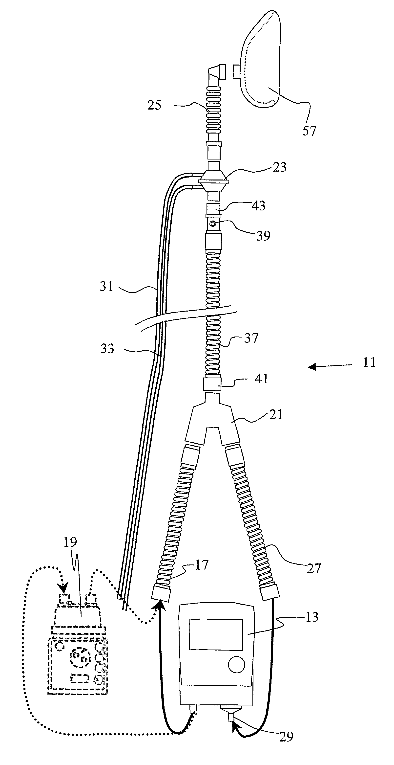
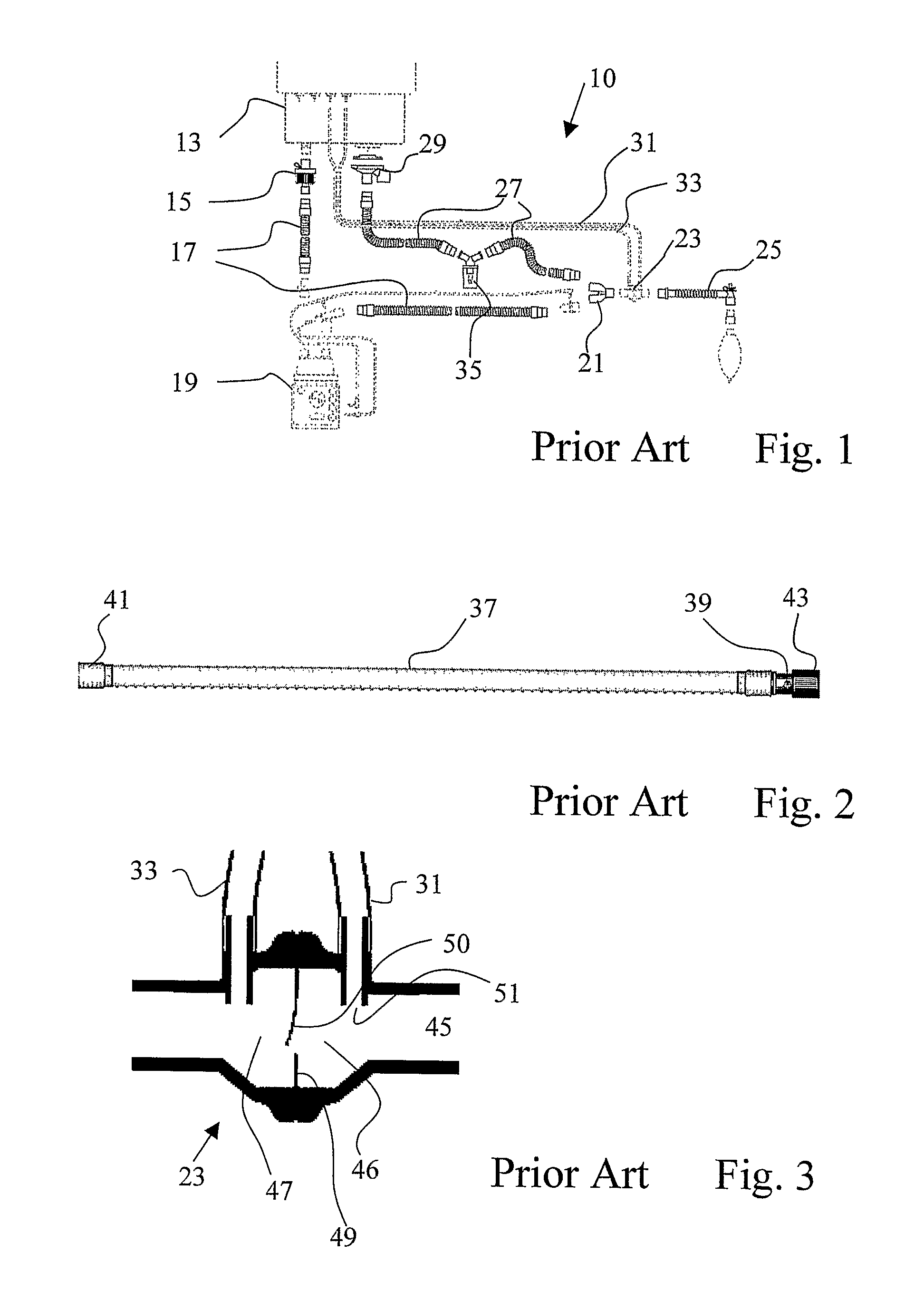
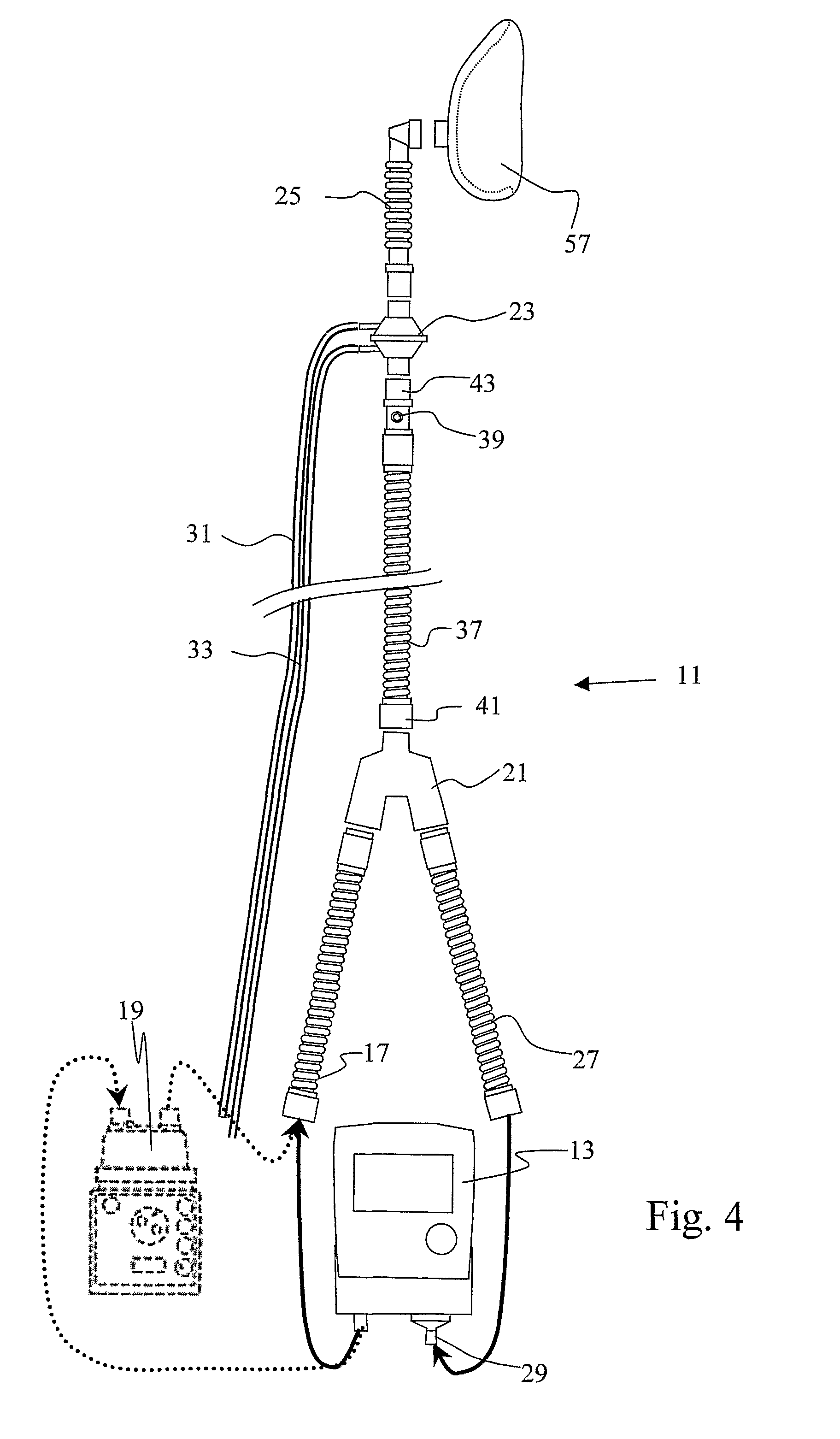
[0029]As described above, prior art includes single tube systems and dual tube systems. The known dual tube system illustrated in FIG. 1 is suitable and configured for invasive ventilation. This dual tube system is therefore to be connected to a ventilation appliance 13 that is suitable for the invasive ventilation. Such an invasive ventilation appliance 13 has two actively controlled valves, namely the inhalation valve (not illustrated, as it is arranged in the interior of the appliance), and the exhalation valve 29. An inhalation tube kit 17 connected to an appliance outlet via a filter 15, and an exhalation tube kit 29 connected to the exhalation valve 29, are connected to a Y piece 21 on their ends facing away from the ventilation appliance 13. The Y piece 21 gathers the two tubes 17 and 27, and combines the same to a single tube 25 leading to the patient. A flow sensor 23 is arranged on the Y piece on the patient side. The flow sensor 23 is connected to the ventilation...


PUM


Abstract

The invention relates to a three-arm tube system for a ventilation appliance suitable for invasive ventilation. Such a ventilation appliance includes an active inhalation valve and an active exhalation valve. The tube system also includes an inhalation tube arm, an exhalation tube arm and a ventilation tube arm for attachment to a mask, and also a flow sensor. A defined leakage is established in the ventilation tube arm, and the flow sensor is arranged between the leakage and the mask. The invention further relates to a ventilation appliance having such a tube system, and to a method for operating the ventilation appliance.

Description

[0001]This application claims priority to International Application PCT / CH2006 / 000631 filed Nov. 9, 2006 and Swiss Patent Application No. 1993 / 05 filed on Dec. 16, 2005, the entirety of which is incorporated by reference.SCOPE OF THE INVENTION[0002]The invention relates to a tube system for ventilation appliances, a ventilation appliance having such a tube system, a method for operating a ventilation appliance, and a method for the mechanical ventilation of patients.PRIOR ART[0003]Dual tube systems are utilized for invasive ventilation. Dual tube systems have an inhalation tube and an exhalation tube that are connected to the patient mask via a Y piece. The inhalation tube is subsequently connected to an inhalation filter protecting the ventilation appliance from contamination. A moisturizing device is possibly arranged between an inhalation tube piece on the device side and an inhalation tube piece on the patient side. On the patient side of the Y piece a flow sensor may be arrange...

Claims


Application Information

Patent Timeline
Patent Type & Authority Patents(United States)
IPC IPC(8): F16K31/02
CPCA61M16/0051A61M16/08A61M16/0833A61M16/204A61M16/205A61M16/06A61M16/16A61M2016/0036A61M2205/15A61M16/107A61M16/024
Inventor BRUNNER, JOSEF
Owner HAMILTON MEDICAL AG
Why Eureka
Try Eureka