Gas turbine systems involving feather seals

a technology of gas turbine engine and seal, which is applied in the direction of machines/engines, stators, light and heating apparatus, etc., can solve the problems of difficult design of feather seals, difficult seal formation between components,

Active Publication Date: 2012-05-22
RTX CORP
View PDF19 Cites 55 Cited by
  • Summary
  • Abstract
  • Description
  • Claims
  • Application Information

AI Technical Summary

Problems solved by technology

Expansion and contraction causes challenges in forming seals between components to prevent gas leakage.
Designing a feather seal can be quite challenging.

Method used


Image

  • Gas turbine systems involving feather seals
  • Gas turbine systems involving feather seals
  • Gas turbine systems involving feather seals

Examples


Embodiment Construction

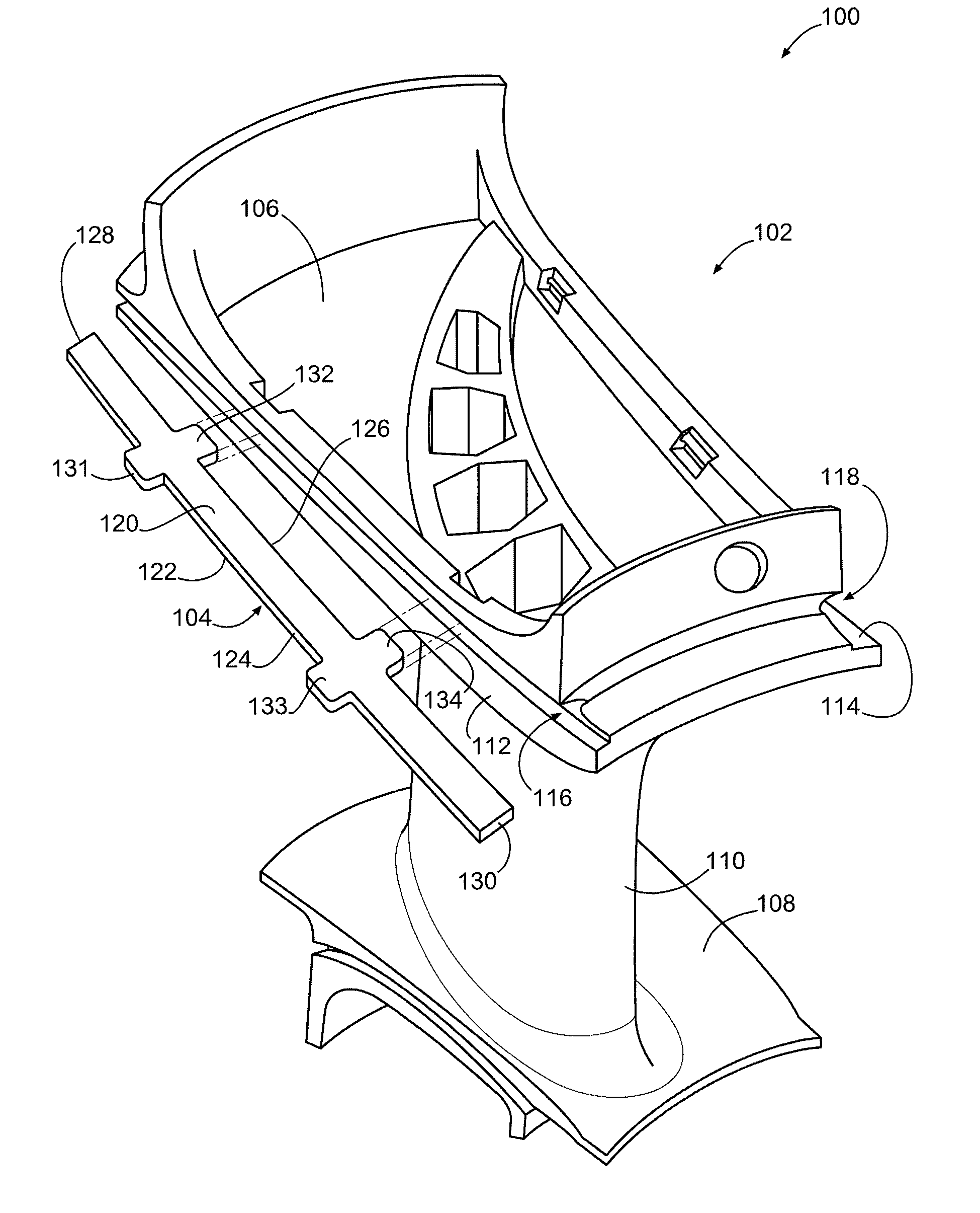
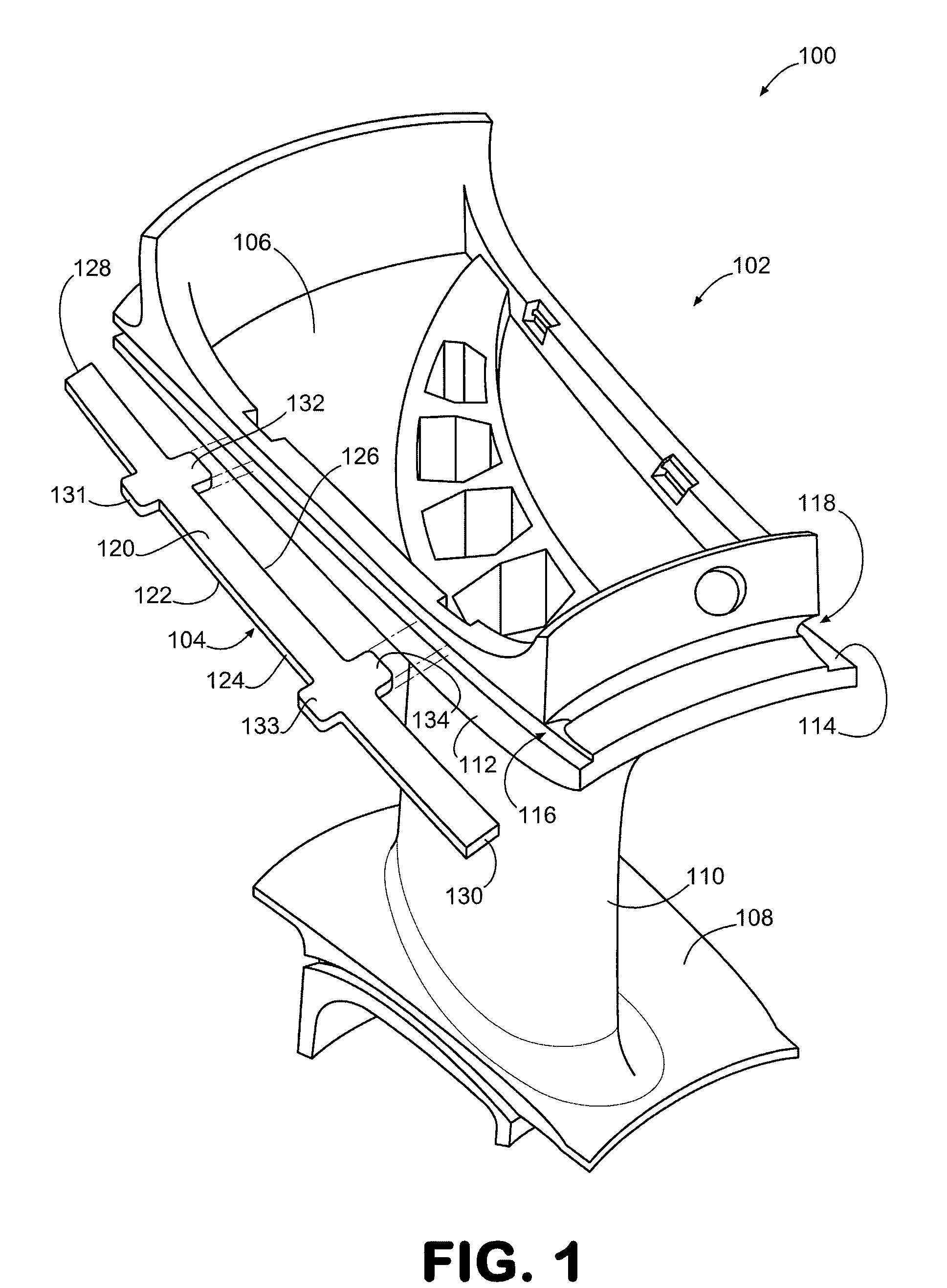
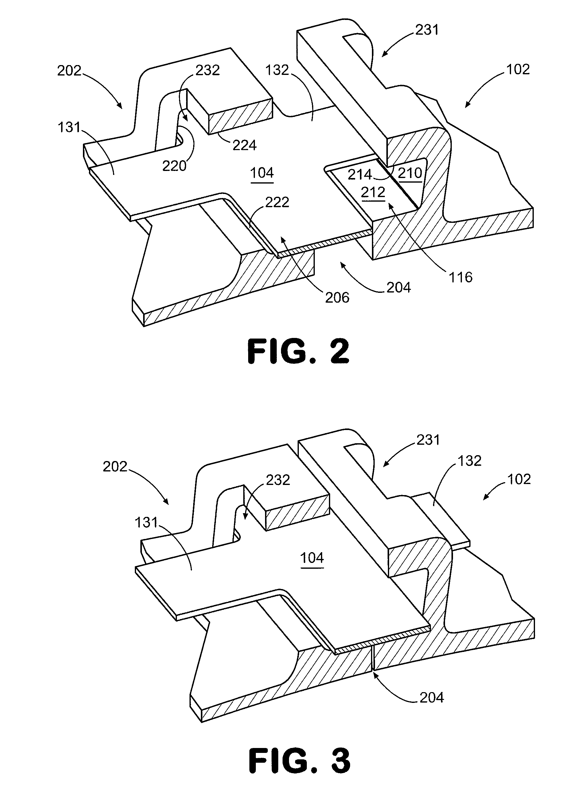
[0018]Several exemplary embodiments of systems involving feather seals will now be described in greater detail. In this regard, at least some of these embodiments involve a feather seal that incorporates at least a first tab that effectively widens the feather seal at the location of the tab. The tab is configured to be received by a corresponding feature of a vane. By way of example, the feature can be a cavity or through-hole into which the tab is inserted. So configured, the feather seal can be designed narrow enough to limit component weight, while the tab effectively widens the feather seal. That is, the tab locally widens the feather seal so that the feather seal does not tend to fall out of place when the vane contracts during cooling. Thus, one or more tabs of a feather seal can be sized for preventing fall-out and remaining portions of the feather seal can be sized to accommodate crushing considerations.

[0019]In this regard, an embodiment of a system involving feather seals...


PUM


Abstract

Systems involving feather seals are provided. A representative vane assembly for a gas turbine engine includes: a first mounting platform having a first slot; a first airfoil extending from the first mounting platform; and a feather seal having opposing faces, a first side extending between the faces, and a first tab, the first tab extending outwardly beyond the first side; the first slot being sized and shaped to receive the feather seal including the first tab.

Description

STATEMENT REGARDING FEDERALLY SPONSORED RESEARCH AND DEVELOPEMENT[0001]The U.S. Government may have an interest in the subject matter of this disclosure as provided for by the terms of contract number N00019-02-C-303 awarded by the United States Air Force.BACKGROUND[0002]1. Technical Field[0003]The disclosure generally relates to seals used in gas turbine engines.[0004]2. Description of the Related Art[0005]Various gas turbine engine components are subjected to heating and cooling cycles that cause the components to expand and contract. Expansion and contraction causes challenges in forming seals between components to prevent gas leakage.[0006]Turbine vane assemblies are examples of components that typically experience expansion and contraction during use. In order to prevent gas leakage between adjacent vanes of a vane assembly, feather seals have been used. A feather seal, which is typically configured as a strip of metal, is positioned between opposing slots of adjacent vanes. No...

Claims


Application Information

Patent Timeline
Patent Type & Authority Patents(United States)
IPC IPC(8): F01D9/04
CPCF01D9/041F01D11/005F01D11/008F05D2260/94F05D2260/941F05D2240/80
Inventor BRIDGES, JR., JOSEPH W.PROPHETER-HINCKLEY, TRACY A
Owner RTX CORP
Why Eureka
Try Eureka