Method and control device for automatically determining a mass of a door system

a technology of automatic determination and control device, which is applied in the direction of program control, electric programme control, instruments, etc., can solve the problems of insufficient mass determination accuracy of less than 10%, half an opening width is available for mass determination, and the inability to determine the mass in an arbitrary operating movement, etc., to simplify the generic method of mass determination

Inactive Publication Date: 2012-05-22
SIEMENS AG
View PDF3 Cites 5 Cited by
  • Summary
  • Abstract
  • Description
  • Claims
  • Application Information

AI Technical Summary

Benefits of technology

[0010]According to the invention, it is now advantageous during an arbitrary movement, that is to say also during normal operation, to establish the door mass by means of the measured and, computationally, via at least two intervals or operating system cycles, without it happening that the movement properties of the door are influenced. Thus, it is possible to operate virtually with arbitrary movement profiles.
[0011]In an advantageous refinement of the invention, a current driving the motor, a motor voltage, in particular an armature voltage, and / or a pulse width modulation signal is / are used as force variable. Since the force variable such as a current driving the motor or a motor voltage, in particular an armature voltage, or else a pulse width modulation signal can be established simply, cost effectively and accurately by measurement, the simple establishment of the motor force variables is very advantageous for the inventive method.
[0017]A further enhancement of the accuracy of the establishment of mass is achieved by virtue of the fact that during the acceleration movement the acceleration firstly starts, beginning with the creeping movement, with a positive value from a first instant and then changes to the creeping movement again with a negative acceleration. By way of example, in a learning movement a ramp with a first gradient is applied over a specific time. The door system or the door is thereby accelerated. After this acceleration time, the door system or the door is braked by a second, negative gradient, which can be substantially steeper than the first gradient, until creeping movement is again achieved. This procedure has the particular advantage that even the masses of very light doors can be established within very small opening widths, and the door comes to rest again in good time before stopping at an end point.
[0022]It is advantageous for safe operation of the door that a kinetic energy of the door, in particular impact energy, is established by means of the mass. By establishing the impact energy, it is possible to set the door system or the motor force or the motor speed in such a way that the impact energy does not exceed a specific limit and therefore does not cause any injuries, for example in the case of malfunction.

Problems solved by technology

It is disadvantageous of the two methods that in the case, for example, of two-leaf doors with a very small opening width, only half an opening width is available for mass determination for a driving operation.
This short distance is not sufficient for determining the mass with a required accuracy of less than 10%.
A further disadvantage is that the mass determination is not possible in an arbitrary operating movement for example during normal opening.

Method used


Image

  • Method and control device for automatically determining a mass of a door system
  • Method and control device for automatically determining a mass of a door system
  • Method and control device for automatically determining a mass of a door system

Examples


Embodiment Construction

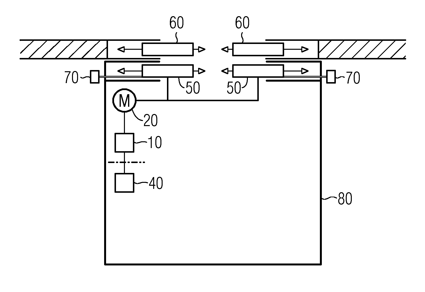
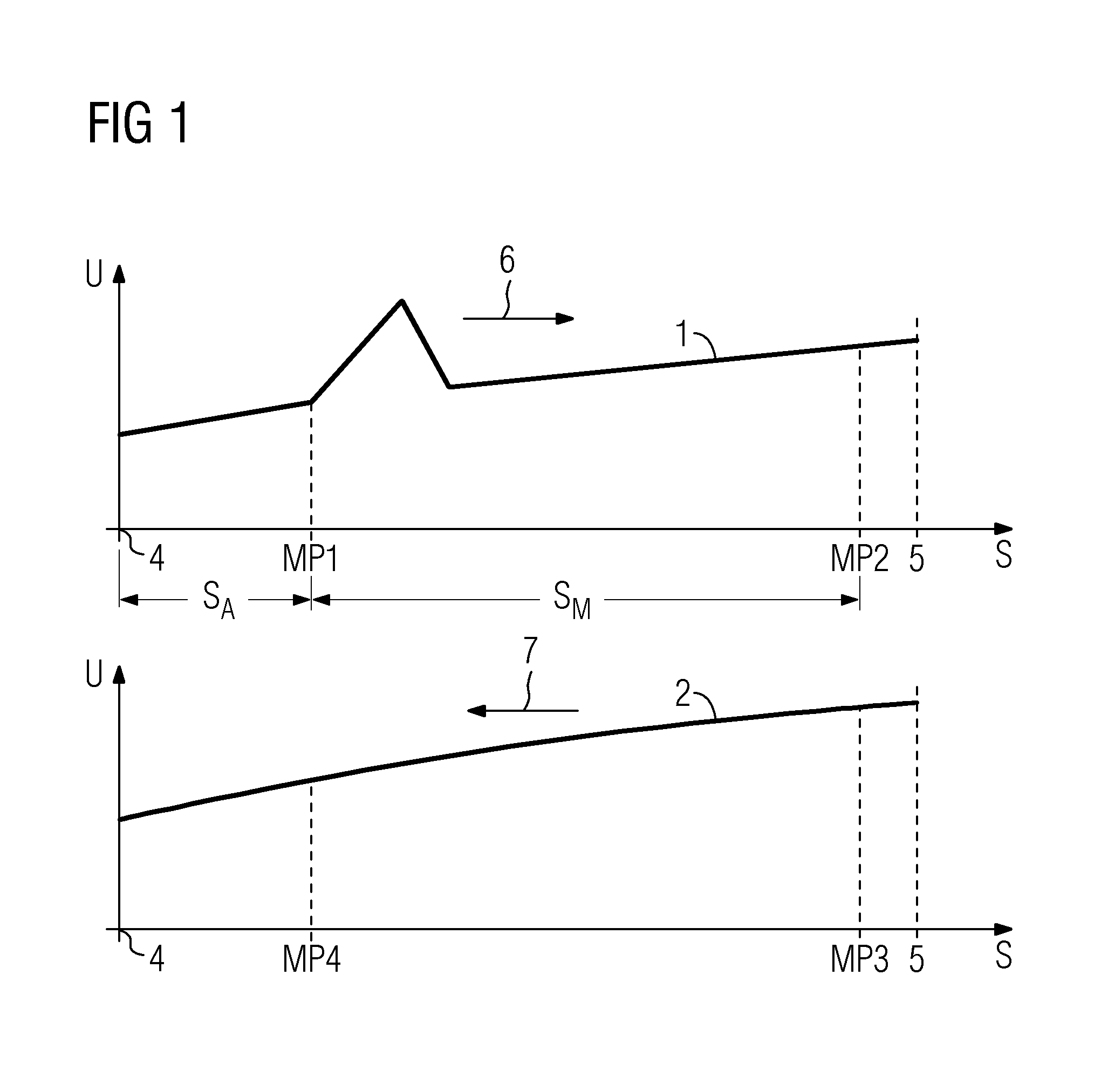
[0028]FIG. 1 shows a motor voltage profile 1 and 2 for an electrically driven door with a mass mT. A motor voltage U is respectively plotted over a movement distance S. The motor voltage profile 1 is illustrated over the movement distance S for a movement in the opening direction 6. The motor voltage profile 2 is illustrated over the movement distance S for a movement in the closing direction 7.

[0029]The door is closed at position 4, this corresponding to a movement distance S=0 mm. After a run up distance of preferably SA=100 mm, starting from a first instant or measuring point MP1 a total current IG is measured for the movement distance of a motor voltage ramp present for 40 operating system cycles Δt with a gradient of one pulse width modulation increment per operating system cycle Δt. A motor current I is summed for this time duration. The motor current I is composed of the measured total current IG minus a friction current IR, I=IG−IR. The door is completely open at position 5....


PUM


Abstract

A method is disclosed for automatically determining an effective mass of a door system that is driven by a motor and has at least one door. In this case a speed change accomplished during an acceleration movement is established, and a force variable, for example the motor current or an armature voltage, influencing the drive force of the motor is summed or integrated during the acceleration movement. The effective door mass is established from the sum or the integral of the force variable and the speed change, the summation or the integration of the force variable being performed over a number of operating system cycles of a control device assigned to the door system. Also described is a control device for automatically determining the effective door mass, having a memory for force variable profiles that is designed in such a way that mass can be established for different force variable profiles in the memory in conjunction with an unchanged program code.

Description

CROSS REFERENCE TO RELATED APPLICATIONS[0001]This application is the US National Stage of International Application No. PCT / EP2006 / 067337, filed Oct. 10, 2006 and claims the benefit thereof. The International Application claims the benefits of German application No. 10 2005 050 125.7 filed Oct. 18, 2005, both of the applications are incorporated by reference herein in their entirety.FIELD OF INVENTION[0002]The invention relates to a method for automatically determining a mass (meff) of a door system that is driven by a motor and has at least one door, a speed change accomplished during an acceleration movement being established, and a force variable influencing the drive force of the motor being summed or integrated during the acceleration movement, and the sum or the integral of the force variable and the speed change (ΔV) being used to determine the mass (meff).[0003]The term door is to be understood equally as a single door leaf, a double door leaf and a rolling door with closing...

Claims


Application Information

Patent Timeline
Patent Type & Authority Patents(United States)
IPC IPC(8): B25J9/22G05B19/42
CPCB66B13/146
Inventor KRAUSE, UWELUDWIG, HEINZNOLTE, UWESONNTAG, GUIDO
Owner SIEMENS AG
Why Eureka
Try Eureka