Kit and method for calibrating large volume 3D imaging systems

a 3d imaging and large volume technology, applied in the field of calibration of large volume 3d imaging systems, can solve the problems of calibration process, few entities could invest, unwieldy and expensive use to be portable, etc., and achieve the effect of convenient movement across the volume, accurate positioning of features, and low cos

Inactive Publication Date: 2020-12-31
NAT RES COUNCIL OF CANADA
View PDF0 Cites 5 Cited by
  • Summary
  • Abstract
  • Description
  • Claims
  • Application Information

AI Technical Summary

Benefits of technology

[0016]Key realizations underpinning this invention were: that having the 3D-IS coordinatize the features of a mobile target plate (MTP), while a range and orientation measurement system (ROMS) onboard the MTP measures a position and orientation of the 3D-IS, gives all information required for calibration at that one point; that a collection of measurement points spanning a FoV of the 3D-IS together can provide in situ calibration over the whole volume of the 3D-IS; that the MTP can be of a size, weight and shape to facilitate movement across the volume and retain accurate positioning of the features of the MTP with respect to the ROMS; and that while the 3D-IS has a large FoV, a low cost ROMS with a far smaller FoV can be used to accurately determine the position of the 3D-IS in a cost effective, and accurate manner. The result is a cost-effective, and low total cost of ownership calibration system, that can be adapted to a wide range of 3D-ISs, having a FoV of 0.8 to 10,000 m3, or 1 to 5,000 m3, more preferably from 1.5 to 2,500 m3, from 2 to 2,000 m3, or from 4 to 1,000 m3.

Problems solved by technology

However, large FoV 3D-ISs are not amenable to such calibration schema, because 1—any object large enough to span the FoV, and dimensionally stable enough to serve as a reference would be too large, heavy, unwieldy and expensive to use to be portable; and 2—producing a calibration process around such a reference object and certifying it, would be so challenging that very few entities could invest in it.
As the reliability of these distributed reference features are very sensitive and the structures are large and heavy, the process for calibration invariably involves moving the 3D-IS to the installation instead of the reverse.
Transporting a 3D-IS to a fixed installation, calibrating it, and returning it, amount to a major cost in down-time for the owner, and increase risks of the 3D-IS being affected adversely during the transport.
While small reference objects are a very easy and cost-effective way to assess whether calibration is accurate in situ, an identified failure of the calibration does not provide any alternative but to move the 3D-IS to the fixed installation.
While a large enclosure over the installation could be conceived, the costs of nearly permanent occupation of a large part of the work-space surrounding the 3D-IS is likely higher than the costs of down-time for delivering the 3D-IS, even to a remote OEM.
Sizes of reference objects are therefore limited by many practical constraints.
Traditional CMMs could be used in place of the installation, but are not portable, and so cannot be brought to the 3D-IS.
Portable CMMs could be brought into position with respect to a 3D-IS, however these do not provide a moving target for imaging by the 3D-IS, especially one that covers any appreciable part of a volume of a large field of view 3D-IS.
A number of portable CMMs could be used, or a single CMM could be repositioned many times, however the work in coordinating each reference position is unwieldy, and may require another system for measuring the positions of the CMM(s).
Of course higher reliability of the second large FoV 3D-IS is already challenged by the fact that the second 3D-IS had to be moved (even with great care and expense) to the work-space.
While simple reference objects can readily identify whether the calibration is, or is not within margins, computing a correction requires many points.
This is not what Applicant considers to be a calibration, as it essentially lacks consistency, systematicity, and a scope of the whole FoV (or at least a relevant range thereof).
Down-time is very expensive for users of industrial metrology, and the small risks of inaccurately certified measurement systems being quantifiable, recalibration may not be provided as regularly as would be ideal.
Recalibration is an on-going expense.
As the means for recertifying large FoV 3D-ISs are not portable, expensive, and delicate instruments, recertification remains a costly perennial problem associated with accurate 3D-ISs.

Method used


Image

  • Kit and method for calibrating large volume 3D imaging systems
  • Kit and method for calibrating large volume 3D imaging systems
  • Kit and method for calibrating large volume 3D imaging systems

Examples


example

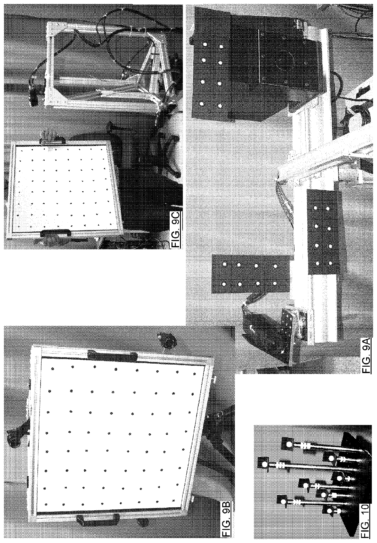
[0086]The present invention has been demonstrated using a structured light 3D-IS (SLS) (FoV of ˜8 m3=2 m×2 m×2 m) as shown in FIG. 9A. The structured light SLS includes a stand, a special purpose projector with optics as taught in Applicant's patent U.S. Pat. No. 8,754,954, a camera, and a computer for collecting data and applying a deconvolution process as explained in Applicant's patent U.S. Pat. No. 8,411,995. The MTP has also been used to calibrate.

[0087]FIG. 9A also shows a series of MTs in the form of standard photogrammetric markers. The markers were applied as photogrammetric stickers (Synthetic paper: Mactac metro label white perm; the dots are 1 cm diameter, and surrounded by black ink printed by Spicers Canada ULC on commercial printer) that were mounted to respective steel plates. The stickers are black with white circular targets having a high absorbance contrast to define the target. The minimum number of sticker is three, typically we use 24 markers. The 24 targets we...


PUM


Abstract

A technique for calibrating a 3D imaging system (3D-IS) that has a large field of view (FoV≥1 m3) involves: a metrological target mounted for fixed positioning with respect to an origin of the 3D-IS; a movable target plate (MTP) with at least one fiducial mark provided on a marked surface thereof; and a range and orientation measurement system (ROMS) on the MTP for measuring a distance and orientation of the MTP relative to the metrological target. The MTP is designed so that when the MTP is manipulated within the 3D-IS's FoV at an angle at which the ROMS can determine its position and orientation relative to the metrological target, at least a majority of the at least one fiducial marks is presented for coordinatization by the 3D-IS. Using such equipment, calibration involves using the measured data and the simultaneous coordinatization to calibrate.

Description

FIELD OF THE INVENTION[0001]The present invention relates in general, to calibration of large field-of-view (FoV) non-contact 3D imaging systems (3D-IS) for industrial dimensional metrology, and in particular, to calibration with a moving target plate (MTP) having an on-board imaging system equipped to determine a position of the 3D-IS while the 3D-IS acquires coordinates of fiducial marks of the target.BACKGROUND OF THE INVENTION[0002]Measuring object positions in space is an increasingly routine activity in industry, and is generally called industrial dimensional metrology. There is always a need for higher accuracy, higher resolution, acquisition of spatial coordinates with lower cost measurement systems and equipment, in less acquisition time, with improved accuracy and precision, and with less equipment setup and calibration time, although various application spaces have different weightings for these requirements. A variety of solutions are known. Generally these solutions var...

Claims


Application Information

Patent Timeline
Patent Type & Authority Applications(United States)
IPC IPC(8): G01B11/24G01B11/22G01B11/00G01S17/89G01S17/894
CPCG01S7/497G01B11/22G01B11/24G01B11/002G01S17/894G01S17/89G01B21/042G01B5/08
Inventor DROUIN, MARC-ANTOINEPICARD, MICHELBOISVERT, JONATHANGODIN, GUYDICAIRE, LOUISE-GUY
Owner NAT RES COUNCIL OF CANADA
Why Eureka
Try Eureka