Systems and methods for powering a gimbal mounted device

a technology of gimbal and mounting device, which is applied in the direction of speed measurement using gyroscopic effects, mechanical instruments, instruments, etc., can solve the problems of aircraft radar system failure and hazardous operation conditions

Active Publication Date: 2012-05-22
HONEYWELL INT INC
View PDF32 Cites 220 Cited by
  • Summary
  • Abstract
  • Description
  • Claims
  • Application Information

AI Technical Summary

Problems solved by technology

Failure of the electrical connections 122, 126 may result in a hazardous operating condition, such as when the radar antenna 102 and the gimbal system 104 are deployed in an aircraft.
Thus, failure of one or both of the electrical connections 122, 126 would cause a failure of the aircraft's radar system.

Method used


Image

  • Systems and methods for powering a gimbal mounted device
  • Systems and methods for powering a gimbal mounted device
  • Systems and methods for powering a gimbal mounted device

Examples


Embodiment Construction

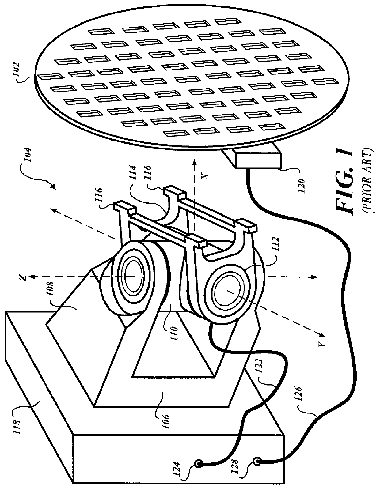
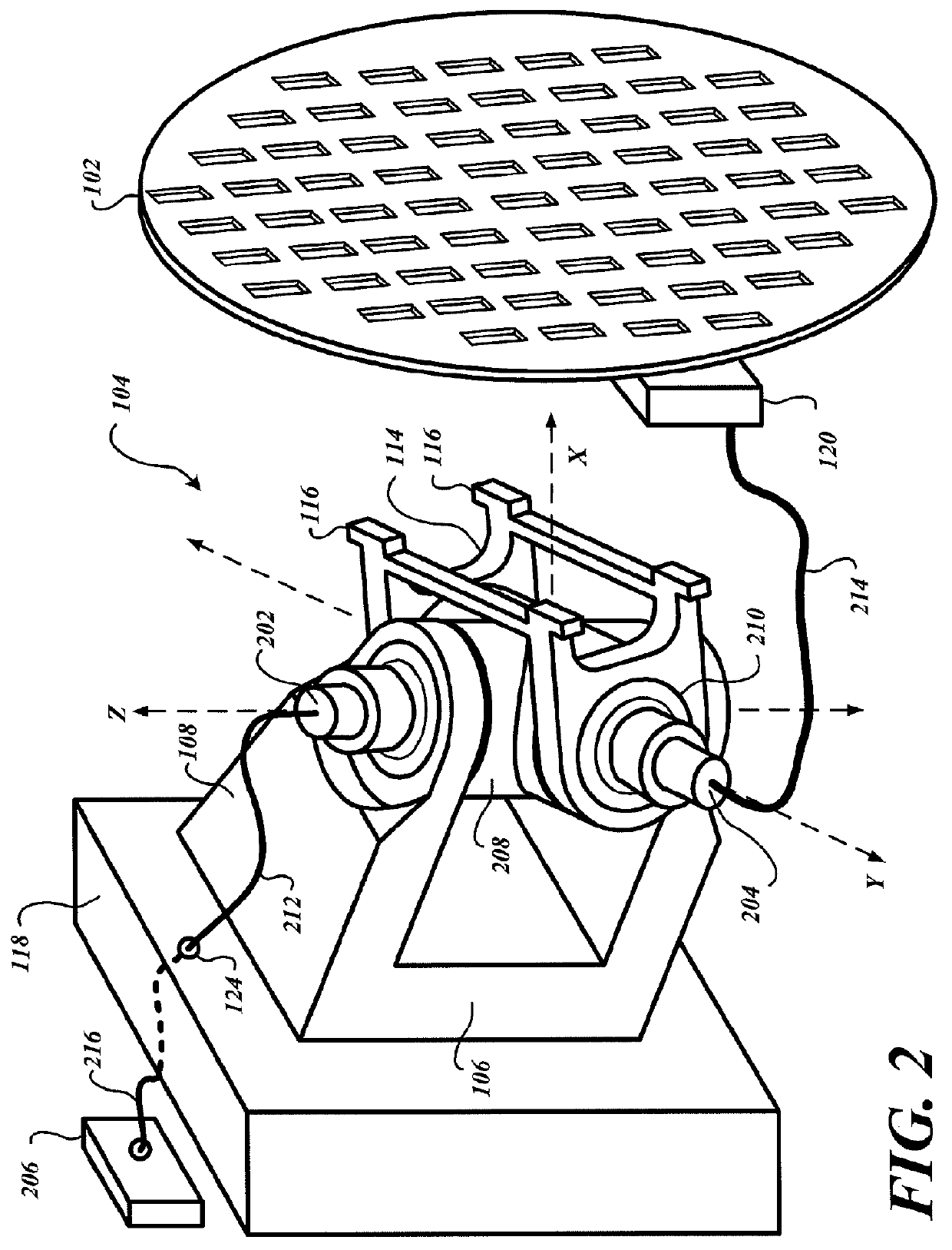
[0018]FIG. 2 is a perspective view of a power transfer gimbal system 200. The exemplary power transfer gimbal system 200 is illustrated as a two-axis gimbal. A first rotary power transformer 202 and a second rotary power transformer 204 are part of a power transfer path between the communication device 120, the antenna 102, and a remotely located power source 206.

[0019]The first rotary power transformer 202 is integrated into, or attached to, a first rotational member 208. The first rotational member 208 is rotationally coupled to the support arms 108 to provide for rotation of the radar antenna 102 about the illustrated Z-axis. The first rotational member 208 is similar to the above-described first rotational member 110. However, the first rotational member 208 is configured to receive and secure the first rotary power transformer 202.

[0020]The second rotary power transformer 204 is integrated into, or attached to, a second rotational member 210. The second rotational member 210 pr...


PUM


Abstract

Gimbal power systems and methods are operable to provide power to a device attached to the gimbal. An exemplary embodiment is configured to rotate a rotational member of the gimbal system about an axis, wherein a stator of a rotary power transformer affixed to the rotational member rotates about the axis, and wherein an end of an electrical connection coupled to a power connector of a rotor winding of the rotary power transformer remains substantially stationary as the stator of the rotary power transformer rotates about the axis.

Description

BACKGROUND OF THE INVENTION[0001]Various devices may be mounted on a single axis, a two-axis, or a three-axis gimbal to facilitate orientation of the device towards a desired direction. FIG. 1 illustrates an exemplary power system for a prior art radar antenna 102 and a two-axis gimbal system 104. When a device, such as the radar antenna 102, is affixed to the gimbal system 104, the device may be pointed in a desired horizontal and / or vertical direction. When the gimbal system 104 includes motors, the device may be oriented on a real time basis.[0002]For example, when the radar antenna 102 is used in a vehicle, such as an aircraft or a ship, the radar antenna 102 may be continuously swept in a back-and-forth manner along the horizon, thereby generating a view of potential hazards on a radar display. As another example, the radar antenna 102 may be moved so as to detect a strongest return signal, wherein a plurality of rotary encoders or other sensors on the gimbal system 104 provide...

Claims


Application Information

Patent Timeline
Patent Type & Authority Patents(United States)
IPC IPC(8): H01Q3/00
CPCH01Q3/08Y10T74/1225
Inventor BUNCH, BRIAN P.MOWRY, STEVEFERGUSON, PAUL
Owner HONEYWELL INT INC
Why Eureka
Try Eureka