Electrical clamping apparatus

a clamping apparatus and electric technology, applied in the direction of gearings, fastening means, toothed gearings, etc., can solve the problems of increasing the size the operation structure of the clamping apparatus is complex, and the production cost of the clamping apparatus is increased, so as to reduce the entire size and improve the grip torque

Active Publication Date: 2018-02-22
ENERGIUM CO LTD +1
View PDF23 Cites 7 Cited by
  • Summary
  • Abstract
  • Description
  • Claims
  • Application Information

AI Technical Summary

Benefits of technology

[0009]The present invention has been made in view of the above problems and provides an electrical clamping apparatus that can reduce an entire size using a motor as a driving source and that can largely improve a grip torque by applying a sliding crank portion and a changed toggle link portion with a driving force transfer mechanism.

Problems solved by technology

However, the conventional clamping apparatus uses an operation cylinder as a power source, and when the operation cylinder and a pneumatic pressure pipe are installed, there is a drawback that a size of the clamping apparatus increases and that an operation structure thereof is complex.
Further, there is a problem that a production cost of the clamping apparatus increases.
Further, in order to clamp a panel having various thicknesses, there is a problem that a driving force transfer mechanism should be controlled to change a grip torque or that a separate clamping apparatus having a driver of different outputs should be prepared.

Method used


Image

  • Electrical clamping apparatus
  • Electrical clamping apparatus
  • Electrical clamping apparatus

Examples


Embodiment Construction

[0029]Hereinafter, exemplary embodiments of the present invention will be described in detail with reference to the accompanying drawings. The same reference numbers are used throughout the drawings to refer to the same or like parts. Further, detailed descriptions of well-known functions and structures incorporated herein may be omitted to avoid obscuring the subject matter of the present invention.

[0030]Hereinafter, an exemplary embodiment of the present invention will be described with reference to FIGS. 1 to 10.

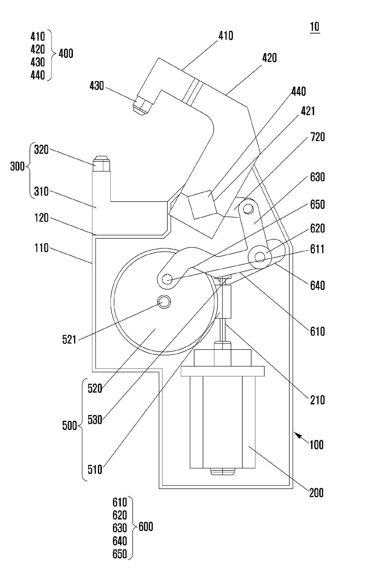
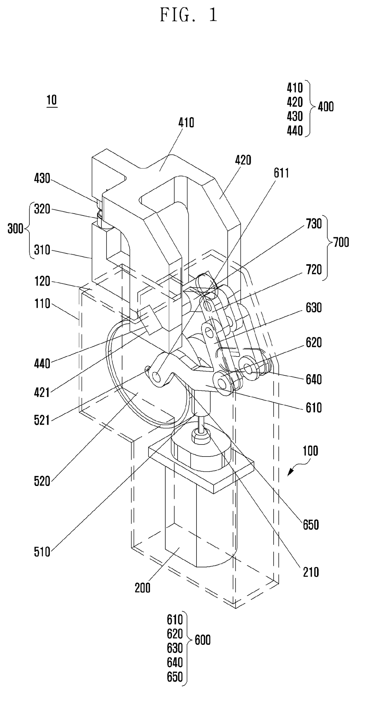
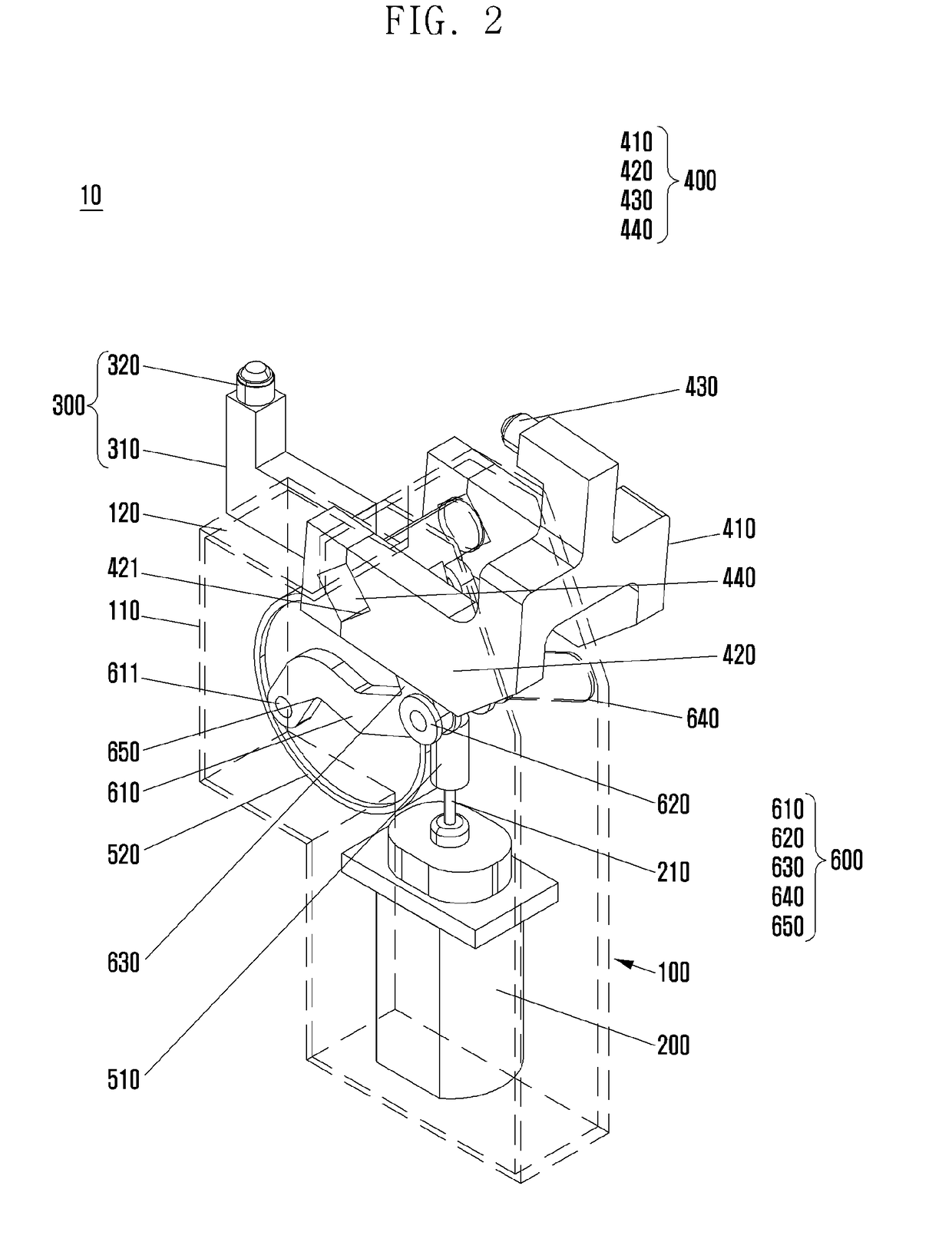
[0031]FIG. 1 is a perspective view illustrating a clamping state in a structure of an electrical clamping apparatus according to an exemplary embodiment of the present invention, and FIG. 2 is a perspective view illustrating an unclamping state in a structure of an electrical clamping apparatus according to an exemplary embodiment of the present invention.

[0032]FIG. 3 is a schematic diagram illustrating a clamping state in a structure of an electrical clamping apparatus a...


PUM


Abstract

An electrical clamping apparatus is provided that can reduce an entire size using a motor as a driving source and largely improve a grip torque by applying a sliding crank portion and a changed toggle link portion with a driving force transfer mechanism. The electrical clamping apparatus for clamping and fixing one side of a panel includes a main body; a driving motor installed within the main body and that generates a driving force; a clamp portion that clamps or unclamps the panel; a toggle link portion connected to the clamp portion and that transfers rotatory power to the clamp portion to rotate the clamp portion; a driving force transfer portion connected to the driving motor to transfer a driving force of the driving motor to the toggle link portion; and a sliding crank portion connected to one side of the toggle link portion to convert a rotational motion of the driving force transfer portion to a linear reciprocating motion and to operate the toggle link portion in a state in which one side thereof is connected to the driving force transfer portion and in which the other side thereof is vertically bent toward the toggle link portion.

Description

PRIORITY[0001]This application claims priority under 35 U.S.C. §119(a) to a Korean Patent Application filed in the Korean Intellectual Property Office on Jul. 28, 2016 and assigned Serial No. 10-2016-0095811, the contents of which are incorporated herein by reference.BACKGROUND OF THE INVENTIONField of the Invention[0002]The present invention relates to a clamping apparatus, and more particularly, to an electrical clamping apparatus that can stably clamp a panel by reducing an entire size using a motor as a driving source and enhancing a grip torque through an enhanced driving force transfer mechanism.Description of the Related Art[0003]In general, a clamping apparatus fixes not to move a panel upon performing a processing work such as cutting, plating, and welding of the panel, has a different grip torque or regulation portion according to a sectional shape of the panel in each processing work, and has a different structure.[0004]A conventional clamping apparatus includes a locator...

Claims


Application Information

Patent Timeline
Patent Type & Authority Applications(United States)
IPC IPC(8): F16B2/18F16B2/10F16H37/12
CPCF16B2/185F16B2/10F16H37/124B25B5/064B25B5/122F16H1/16F16H21/44F16H37/12B25B5/04B25B5/12B25B5/16B25B11/00
Inventor KIM, JONGWONPARK, SUMINBAE, JANGHOBAK, JEONGAECHU, KYUNGSUNGKANG, JUNGHUNERKHES, BILEGT
Owner ENERGIUM CO LTD
Why Eureka
Try Eureka