Devices for position-controlled stopping of rotating components with position-controlled drive mechanisms in the case of voltage loss

a technology of position control and rotating components, which is applied in the direction of multiple dynamo-electric motor speed regulation, ac motor stoppers, dynamo-motor starters, etc., and can solve the problem of not knowing which part of the regulator the battery is connected to and what type of motor is used

Inactive Publication Date: 2006-03-28
KOENIG & BAUER AG
View PDF20 Cites 6 Cited by
  • Summary
  • Abstract
  • Description
  • Claims
  • Application Information

AI Technical Summary

Benefits of technology

[0009]In a second preferred embodiment of the present invention, some components of a conventional UPS can also be eliminated in that only the energy storage device of the UPS is used.

Problems solved by technology

However, this publication discloses neither which part of the regulator the battery is connected to nor what type of motor is used.

Method used


Image

  • Devices for position-controlled stopping of rotating components with position-controlled drive mechanisms in the case of voltage loss
  • Devices for position-controlled stopping of rotating components with position-controlled drive mechanisms in the case of voltage loss
  • Devices for position-controlled stopping of rotating components with position-controlled drive mechanisms in the case of voltage loss

Examples


Embodiment Construction

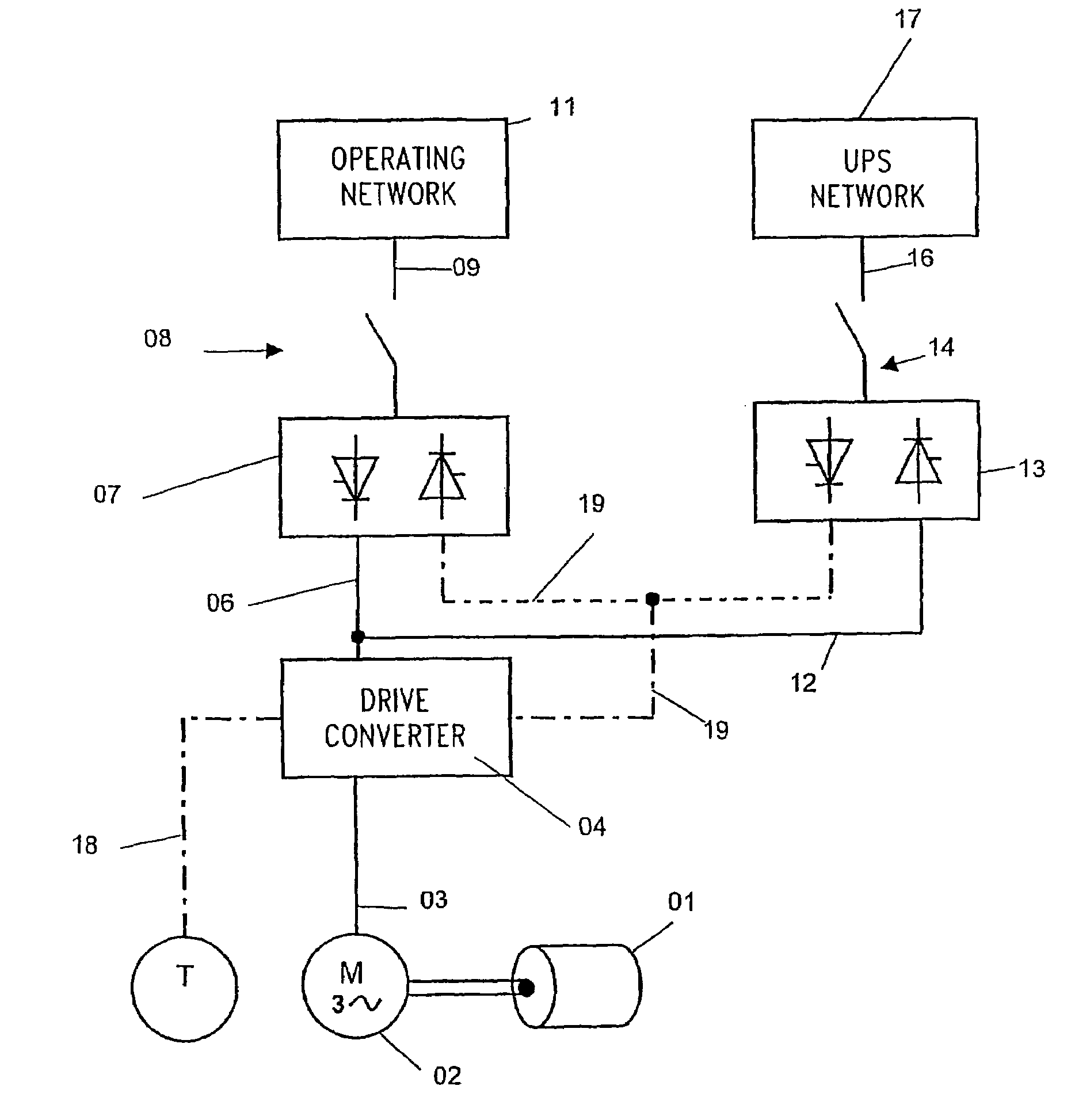
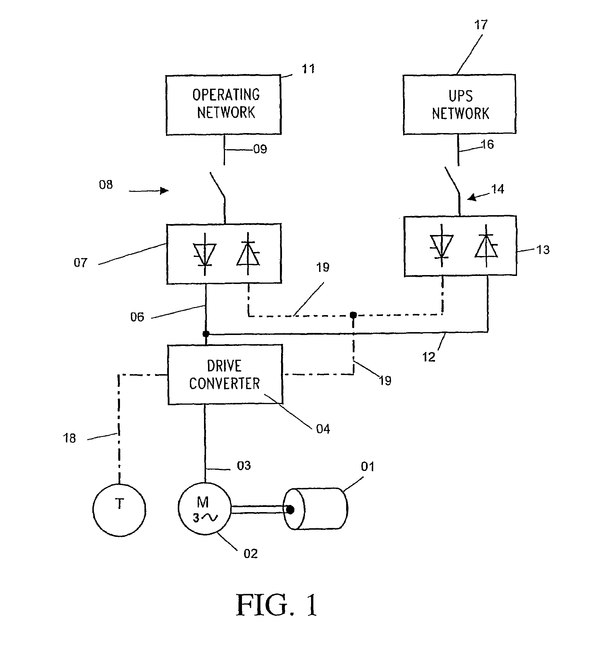
[0013]Referring initially to FIG. 1, a rotating component 01, such as, for example, a folding apparatus of a web-fed rotary printing press, is driven in a speed-controlled and position-controlled manner by the use of a shaftless drive mechanism 02, such as an electric motor. The electric motor 02, which is preferably a three-phase motor, receives its energy supply via a line 03 from a generally conventional drive converter 04, which is connected, via a line 06, an electronic switch 07, a network-disconnecting switch 08, and a line 09 to an operating network 11, of, for example, 400 Volt three-phase current.

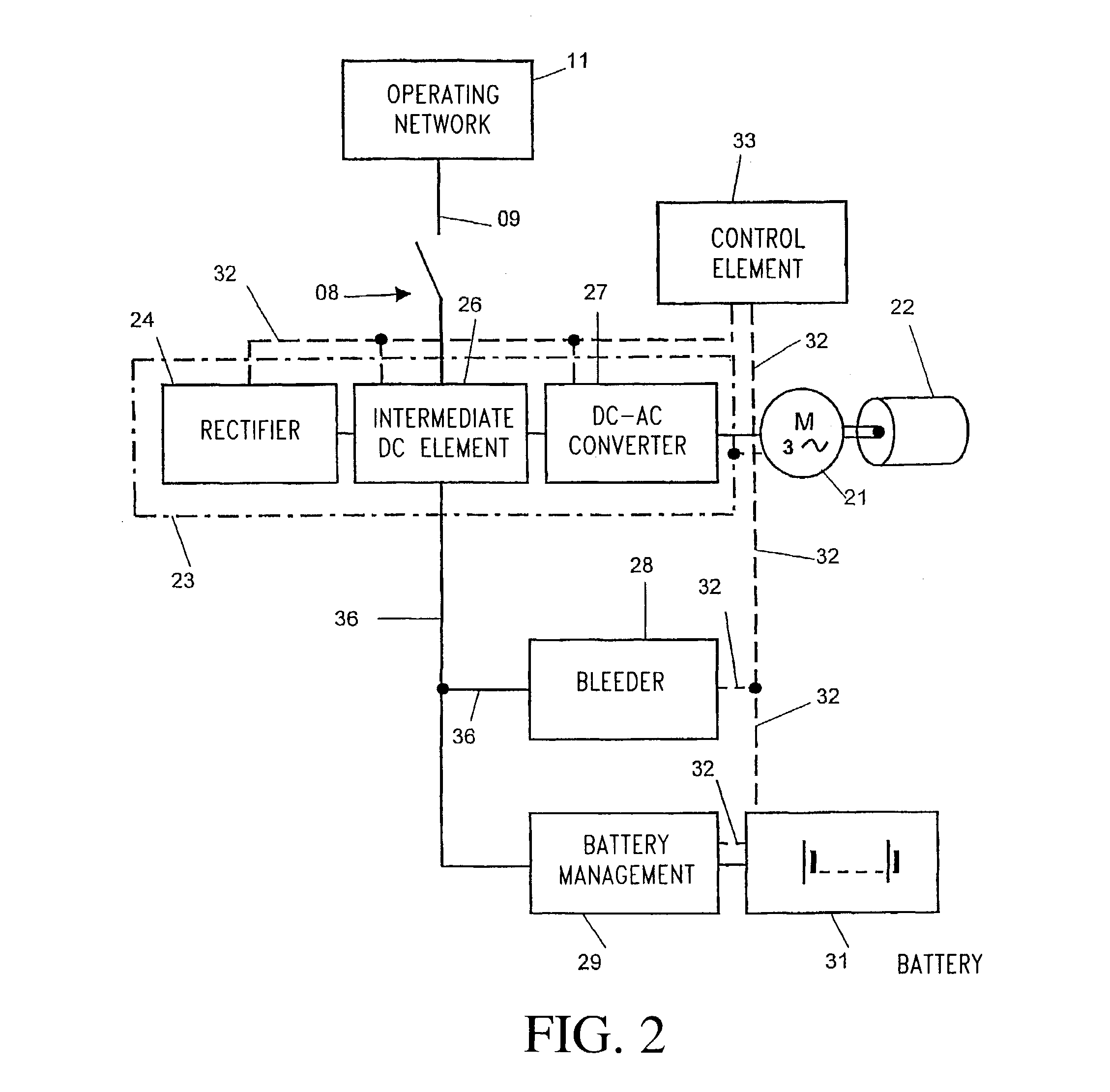
[0014]The drive converter 04 can be comprised at least of sub-units, which are not specifically shown, such as a rectifier, an intermediate DC circuit, a DC-AC converter, and a control element. In addition, the drive converter 04 can contain a dropping resistor or bleeder in order to convert excess braking energy into heat if necessary.

[0015]For the eventuality of a voltage loss o...


PUM


Abstract

The position-controlled stopping of rotating components of shaftless drive mechanisms, in the case of a loss of voltage, is accomplished by the provision of an external connectable network. That external connectable network supplies the process power which is missing due to a loss of rotational power in the event of a voltage loss.

Description

[0001]The present invention is directed to a device for position-controlled stopping of rotating components with position-controlled drive mechanisms in the case of a voltage loss. The rotating component is supplied with a necessary differential energy from an external network.BACKGROUND OF THE INVENTION[0002]In the case of a voltage loss, the drive mechanisms of a production train, such as the drive mechanisms of a web-fed rotary printing press, are shut down in a controlled angularly synchronous manner in order to thus prevent a rupture or a breakage of the web. Units with excess kinetic energy, such as, for example, rotating centrifugal masses, are brought to a stop within the normal rapid stop sequence through controlled reduction of the kinetic energy, for example, by the use of braking resistances, such as so-called bleeders.[0003]Those units such as, for example, folding apparatuses, which cannot themselves supply enough rotational energy in relation to the required process e...

Claims


Application Information

Patent Timeline
Patent Type & Authority Patents(United States)
IPC IPC(8): G05B11/01H02J11/00H02J7/34H02J9/06H02P5/00
CPCH02P5/00H02P3/24
Inventor MARKERT, NIKOLAUS
Owner KOENIG & BAUER AG
Why Eureka
Try Eureka