Flow Stream Momentum Conversion Device Power Rotor

a technology of momentum conversion and flow stream, which is applied in the direction of electric generator control, renewable energy generation, greenhouse gas reduction, etc., can solve the problems of shaft torque increase, rotational speed decrease, etc., and achieve optimal blade curvature and height, maximize shaft power, and maximize inlet stream area

Inactive Publication Date: 2009-01-15
NAIL JASPER M
View PDF21 Cites 7 Cited by
  • Summary
  • Abstract
  • Description
  • Claims
  • Application Information

AI Technical Summary

Benefits of technology

[0008]The geometrical considerations maximize inlet stream area and concentrate the exiting fluid at the outer circumference area of the working volume. The fluid exits the working volume into the original stream flow but orthogonal to the flow so that there is no detrimental reaction with the original flow at discharge. The design also optimizes the blade curvature and height. This maximizes the shaft power realized from the inlet fluid flow stream.

Problems solved by technology

Power is extracted from the device as mechanical loading is applied to the rotating shaft resulting in a decrease in rotational speed and an increase is shaft torque.

Method used


Image

  • Flow Stream Momentum Conversion Device Power Rotor
  • Flow Stream Momentum Conversion Device Power Rotor
  • Flow Stream Momentum Conversion Device Power Rotor

Examples


Embodiment Construction

[0016]The utility, uniqueness, and non-obvious aspects in the construction and applications of the Flow Stream Momentum Conversion Device (FSMCD) Power Rotor will now be described, while referring to the drawings referenced.

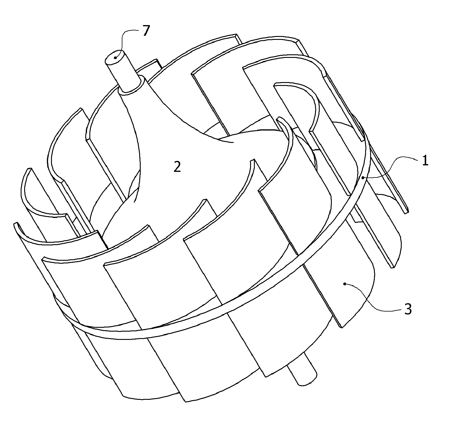
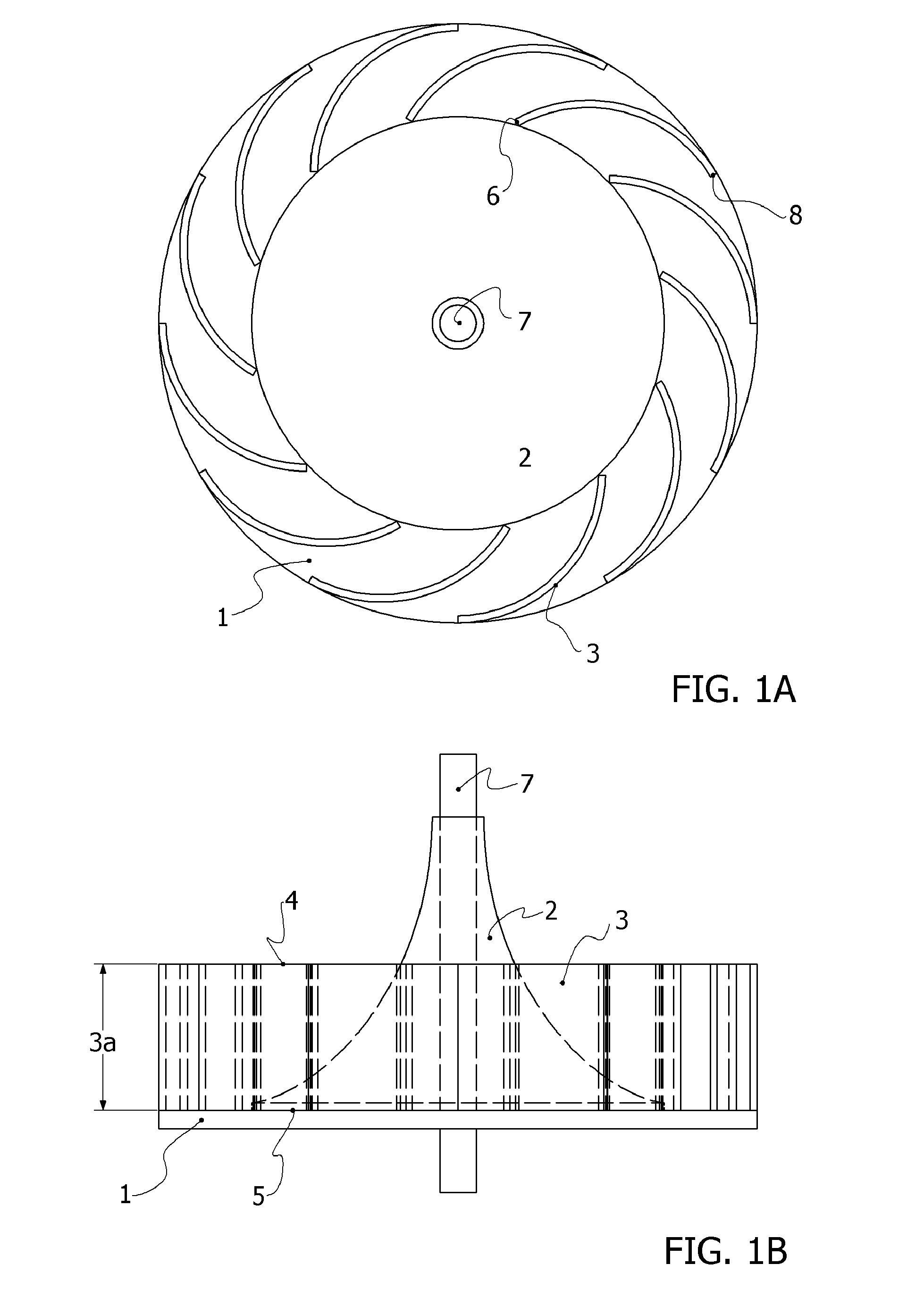
[0017]Referring to the plan view of the upstream end of a unidirectional FSMCD depicted in FIG. 1A, flow of fluid in (axially) and out (circumferentially) will cause the device to rotate in the counter clockwise (CCW) direction. The curved blades 3 configured as shown are, arbitrarily, configured with Left Handed orientation. The device may also be equipped with Right Handed blade orientation, which results in clockwise (CW) rotation of the device.

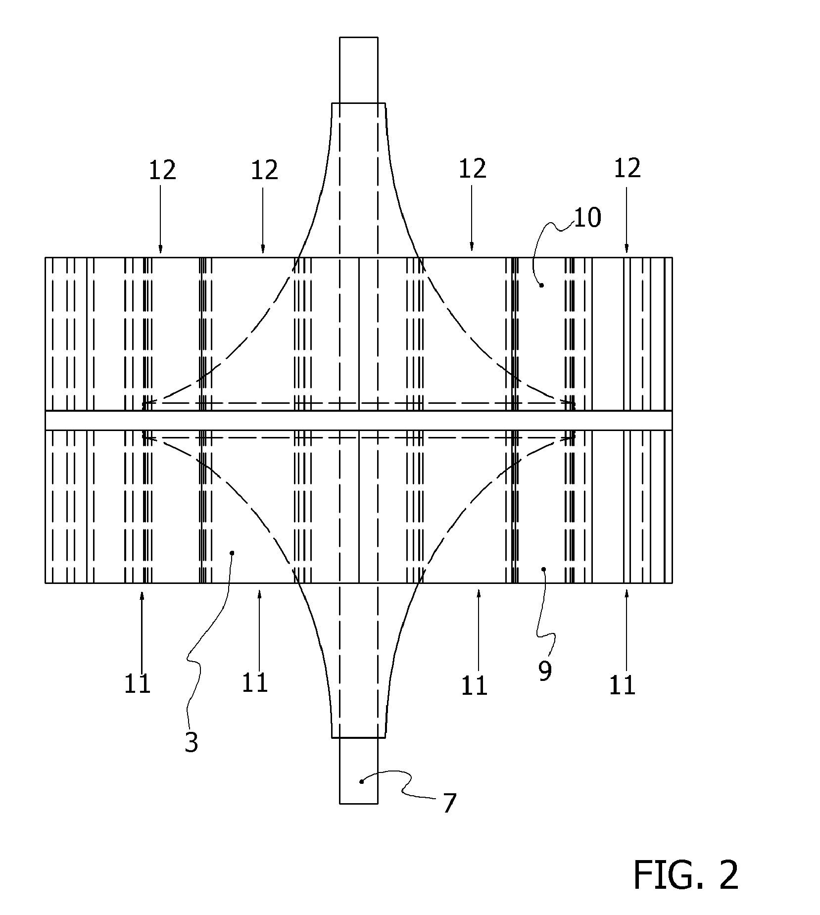
[0018]This embodiment of the invention incorporates a barrier plate 1 that is circular in shape, lying in a plane orthogonal to the inlet stream flow, attached to a shaft 7. The barrier plate 1 defines the axially directed cross sectional area of the device. This embodiment may or may not contain a radial fluid deflecto...


PUM


Abstract

A device known as a Flow Stream Momentum Conversion Device (FSMCD) Power Rotor has been invented. The device makes use of the principle of Conservation of Momentum to convert fluid stream input momentum to device rotational power. A unique and non-obvious aspect of the fluid momentum conversion is circumferential discharge. This aspect maximizes power conversion in a given cross section of open stream flow. Power is extracted from the device as mechanical loading is applied to the rotating shaft resulting in a decrease in rotational speed and an increase is shaft torque. The device has practical usage in both wind and water flows. Under the condition of zero rotor shaft loading the device may be configured to make linear stream measurement of flow speed. This invention has applications in utilizing both unidirectional and bidirectional “fluid stream” flow. It is especially effective in tidal and wave action applications.

Description

CROSS REFERENCE TO RELATED PATENT APPLICATION[0001]This application claims the benefit of U.S. Ser. No. 60 / 958,686 Filed Jul. 9, 2007 under 35 U.S.C. § 119(e) (hereby specifically incorporated by reference in its entirety).FIELD OF THE INVENTION[0002]The present invention relates to power extraction from slow to moderately fast moving fluid streams. In particular, it relates to rotary devices such as windmills, turbines, and propellers that convert moving wind or water stream energy into useable shaft power.BACKGROUND OF THE INVENTION[0003]Both wind and water streams have for centuries produced useable shaft power through the conversion of kinetic energy of stream flow to rotary motion. These sources of energy continue to be desirable choices since they are renewable and they are environmentally friendly. High-speed fluid flows provide most of the usage. There are significant advantages in power conversion of high-speed stream flow as compared to lower flow rates. These advantages s...

Claims


Application Information

Patent Timeline
Patent Type & Authority Applications(United States)
IPC IPC(8): F03D9/00
CPCF03B3/125Y02E10/74Y02E10/223F03D3/061Y02E10/20
Inventor NAIL, JASPER M.
Owner NAIL JASPER M
Why Eureka
Try Eureka