Supercharge Your Innovation With Domain-Expert AI Agents!

Device and method for deactivating safety function

Active Publication Date: 2012-05-22
ROBERT BOSCH GMBH
View PDF8 Cites 8 Cited by
  • Summary
  • Abstract
  • Description
  • Claims
  • Application Information

AI Technical Summary

Benefits of technology

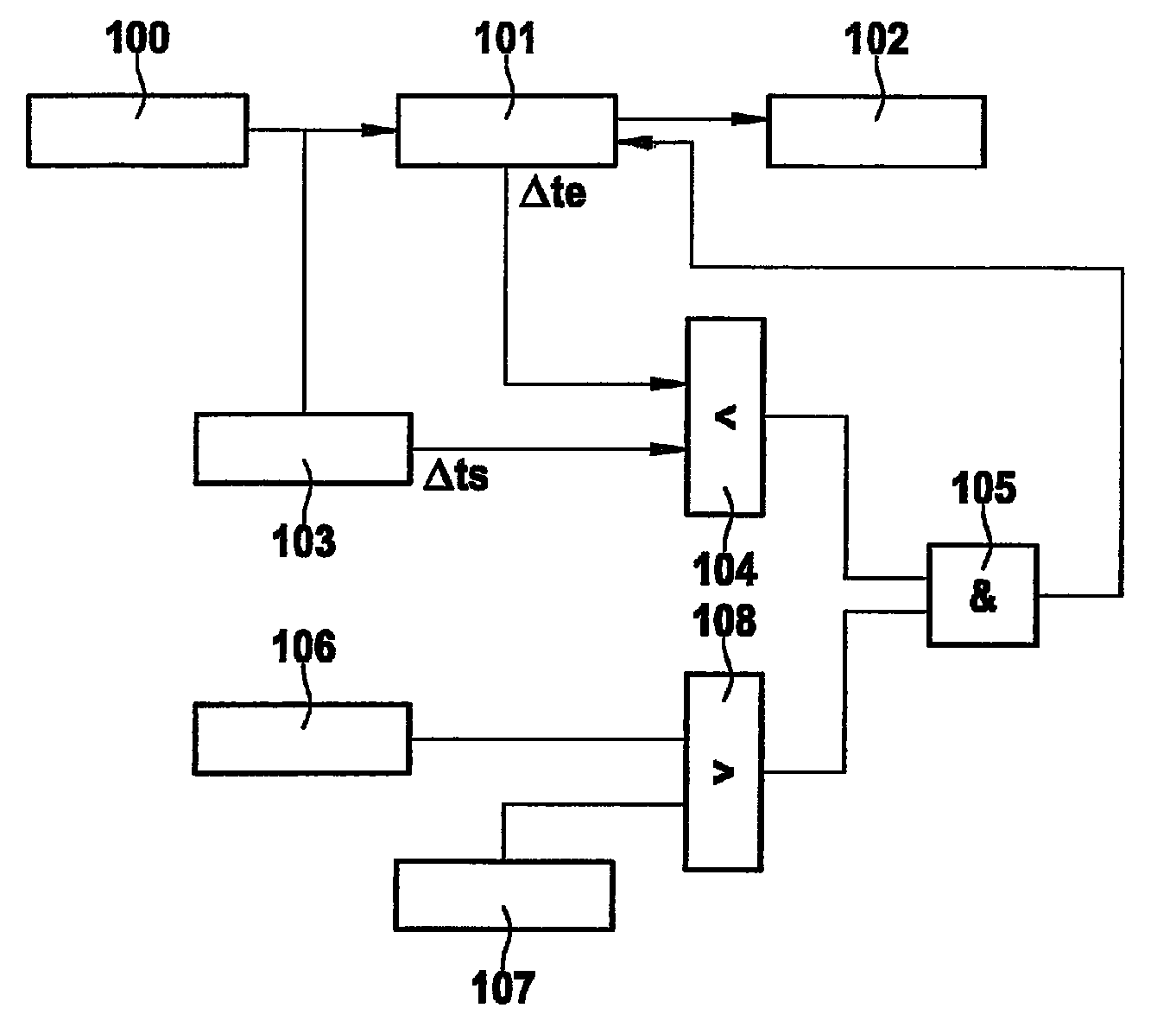
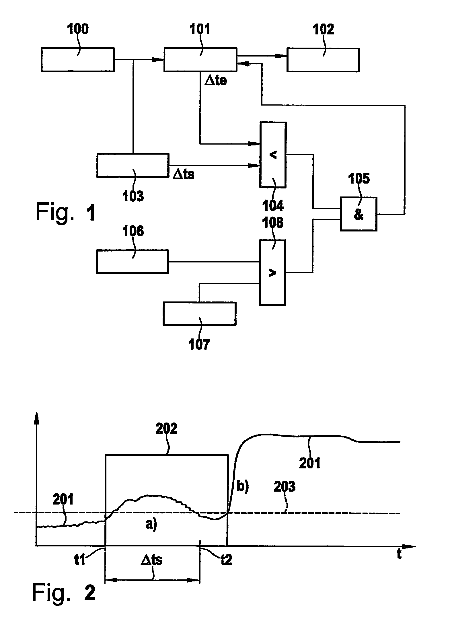
[0005]Example embodiments of the present invention provide a method for deactivating a safety function in a motor vehicle. An aspect hereof is that after being activated, the safety function may be deactivated by the driver only after a dead time has elapsed. Thus, a situation is avoided in which an imprudent panic reaction or overreaction of the driver leads to a deactivation of the safety function.

Problems solved by technology

Today, these systems are designed such that they trigger only when an accident is unavoidable.

Method used


Image

  • Device and method for deactivating safety function
  • Device and method for deactivating safety function

Examples


Embodiment Construction

[0017]Current safety systems are frequently not able to be overruled. It is an aspect of example embodiments of the present invention to allow a safety system to be overruled by the driver. Conventional strategies for deactivating vehicle systems such as ACC address “normal” driving situations in which corresponding driver-related operating variables are to be expected. However, if a safety function that intervenes in an emergency situation is to be examined, other responses on the part of the driver must be expected. In particular, in the event of a suddenly occurring emergency situation, a startle reaction on the part of the driver may be assumed. Possible manners of responding include no reaction at all to the event, delayed reaction to the event, or overreaction, for example.

[0018]For this reason, driver-related operating variables that occur during this startle reaction do not necessarily correspond with a targeted driver reaction and therefore may be interpreted only with diff...


PUM


Abstract

In a method for deactivating a safety function in a motor vehicle after being activated, the safety function may be deactivated by the driver only after a dead time has elapsed.

Description

FIELD OF THE INVENTION[0001]The present invention relates to a method and device for deactivating a safety function.BACKGROUND INFORMATION[0002]Today, a plurality of assistance and safety systems help drivers manage the task of driving. These include systems such as ABS and ESP, ACC, airbags and other restraint systems. Today, assistance systems are designed in such a manner that the driver maintains full control over the vehicle at all times. For example, this is achieved in that the driver deactivates the system in question by intervening personally. Thus, for example, an ACC is switched off as soon as the driver brakes or activates the gas pedal.[0003]In the future, systems based on environment sensor systems, such as the automatic emergency braking, will also find their way into vehicles. Today, these systems are designed such that they trigger only when an accident is unavoidable. Thus, it is not necessary for them to be able to be overruled.[0004]If safety systems are to inter...

Claims


Application Information

Patent Timeline
Patent Type & Authority Patents(United States)
IPC IPC(8): G05D3/00
CPCB60T7/12B60T2201/02B60T2201/024
Inventor LICH, THOMASEWERHART, FRANKMARCHTHALER, REINERSTABREY, STEPHANGEORGI, ANDREAS
Owner ROBERT BOSCH GMBH
Features
  • R&D
  • Intellectual Property
  • Life Sciences
  • Materials
  • Tech Scout
  • Unparalleled Data Quality
  • Higher Quality Content
  • 60% Fewer Hallucinations
Learn More