Device for detecting response characteristics of sensor

a sensor and response technology, applied in the direction of electrical control, process and machine control, etc., can solve the problems of difficult to precisely detect the deterioration of the air-fuel ratio feedback controllability, the failure of the sensor, and the deterioration of the engine performance, so as to improve the precision for diagnosing the failure condition of the sensor and improve the precision for controlling the air-fuel ratio

Active Publication Date: 2005-09-29
DENSO CORP
View PDF3 Cites 36 Cited by
  • Summary
  • Abstract
  • Description
  • Claims
  • Application Information

AI Technical Summary

Benefits of technology

[0007] In order to achieve the above first object according to the invention, a timing of changing the amount of the fuel fed to an internal combustion engine is determined by fuel changing timing determining means, the behavior of the sensor output before and after the change in the amount of feeding the fuel is monitored by the reply characteristics detecting means and the response characteristics of the sensor are detected being divided into a dead time from when the amount of feeding the fuel is changed until when the sensor output starts changing and the subsequent n-order delay characteristics (n is a positive integer) representing a change in the sensor output characteristics. According to this constitution, the response characteristics of the sensor are detected being divided into the dead time and the n-order delay characteristics. It is therefore made possible to detect the response characteristics (dead time and n-order delay characteristics) on which the design of the air-fuel ratio feedback control system is based, and to precisely detect the deterioration in the air-fuel ratio feedback controllability caused by the deteriorated response characteristics of the sensor or by the faulty sensor.
[0008] In order to achieve the above second object, further, the presence of a fail condition in the sensor is determined by fail condition determining means based on at least either the dead time or the n-order delay characteristics detected by the step response characteristics detecting means. That is, a relationship between the dead time and the n-order delay characteristics varies depending upon the fail mode of the sensor. Therefore, if the fail condition is diagnosed being divided into the dead time and the n-order delay characteristics, a fail mode which could not be detected so far can now be detected contributing to improving the precision for diagnosing the fail condition of the sensor.
[0009] To achieve the above third object, further, the air-fuel ratio feedback control parameter may be varied or corrected based on at least either the dead time or the n-order delay characteristics detected by the step response characteristics detecting means. Therefore, the air-fuel ratio feedback control parameter can be properly corrected depending upon a change in the response characteristics (dead time and n-order delay characteristics) in the modern general air-fuel ratio feedback control systems, to improve the precision for controlling the air-fuel ratio.

Problems solved by technology

Therefore, if the response characteristics of the sensor vary due to deteriorated characteristics of the sensor that detects the air-fuel ratio of the exhaust gas or due to the faulty sensor, the precision for detecting the air-fuel ratio is deteriorated and, hence, the precision for controlling the air-fuel ratio is deteriorated, causing a deterioration in the engine performance.
It is therefore difficult to precisely detect the deterioration in the air-fuel ratio feedback controllability caused by the deteriorated response characteristics of the sensor or by the faulty sensor.
Further, the above method is not detecting the response characteristics (dead time and the 1st-order delay characteristics or the 2nd-order delay characteristics) on which the design of the air-fuel ratio feedback control system is based.
It is therefore difficult to detect the response characteristics or to correct the air-fuel ratio feedback control parameter relying upon the response characteristics that are detected.

Method used


Image

  • Device for detecting response characteristics of sensor
  • Device for detecting response characteristics of sensor
  • Device for detecting response characteristics of sensor

Examples


embodiment 1

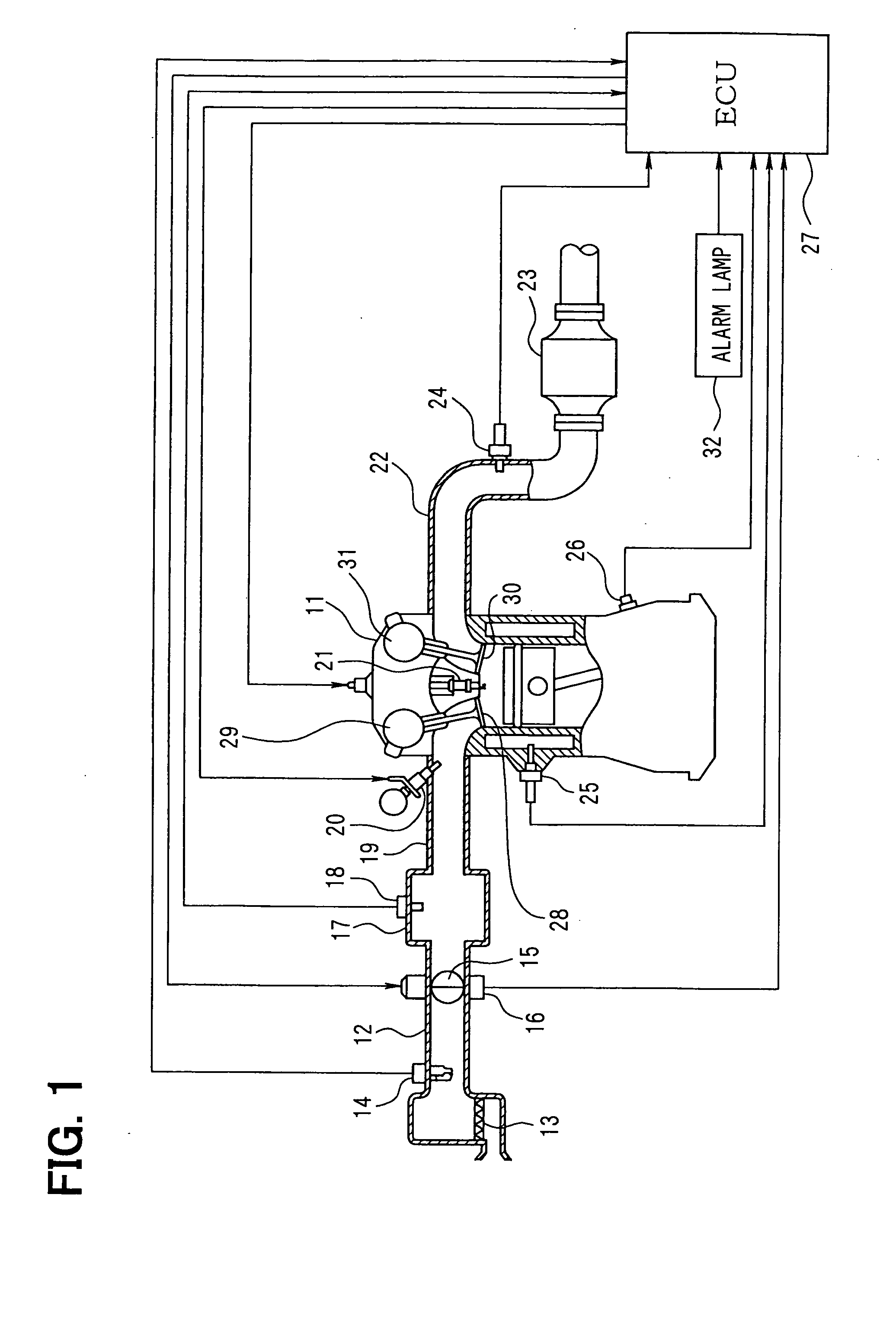
[0029] An embodiment 1 in which the invention is applied to an intake port injection engine will now be described with reference to FIGS. 1 to 9. First, FIG. 1 schematically illustrates the constitution of an engine control system as a whole. An air cleaner 13 is provided at the most upstream portion of an intake pipe 12 of an engine 11 which is an internal combustion engine, and an air flow meter 14 is provided on the downstream of the air cleaner 13 for detecting the amount of the air taken in. On the downstream of the air flow meter 14, there are provided a throttle valve 15 of which the opening degree is adjusted by a motor 10 and a throttle-opening sensor 16 for detecting the throttle opening degree. Further, a surge tank 17 is provided on the downstream of the throttle valve 15, and an intake pipe pressure sensor 18 is provided in the surge tank 17 to detect the pressure in the intake pipe. The surge tank 17 is further provided with an intake manifold 19 for introducing the ai...

embodiment 2

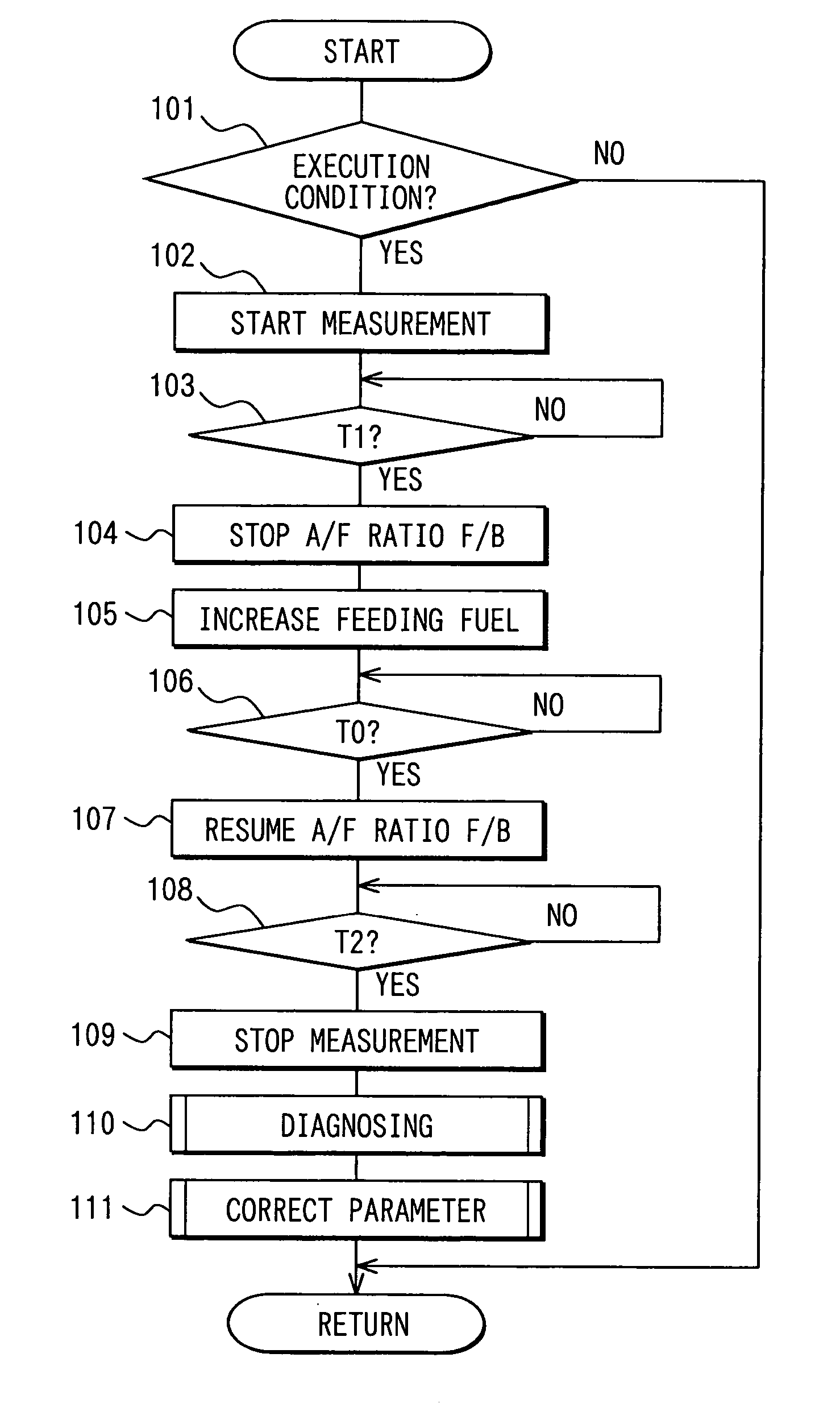
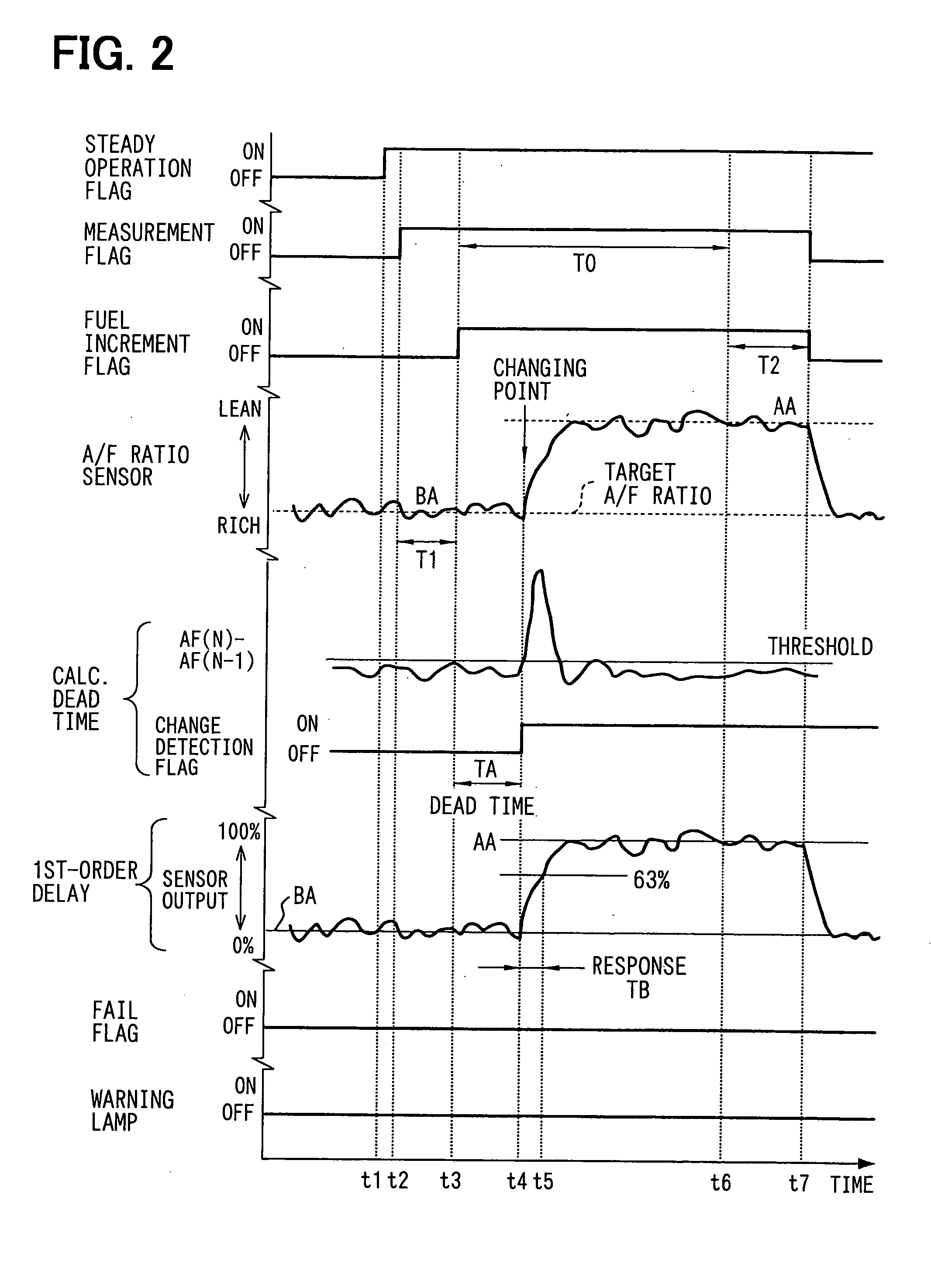
[0083] In the above embodiment 1, the response characteristics of the air-fuel ratio sensor 24 are detected by shifting the air-fuel ratio stepwise toward the rich side (or the lean side) by increasing (or decreasing) the amount of feeding the fuel by step inputting during the steady operation of the engine 11. In the embodiment 2 of the invention, however, the response characteristics (dead time TA and the response time TB) of the air-fuel ratio sensor 24 are detected by utilizing a change in the amount of feeding the fuel when the target air-fuel ratio is changed over to the rich side or the lean side and the amount of feeding the fuel is varied (increased or decreased) during the steady operation of the engine 11.

[0084] In this embodiment 2, a routine for calculating the dead time of FIG. 10 is periodically executed while the engine is in operation to calculate the dead time in a manner as described below. When the routine starts, it is determined at step 211, first, if the dead...

embodiment 3

[0091] In the above embodiments 1, 2, the point where the gradient of change in the sensor output exceeds the threshold value after the amount of feeding the fuel has been changed is detected as a point of start of change. It is, however, also allowable to detect response times of a number of not less than n+1 to estimate an approximation (transfer function) of a curve of a change in the sensor output of the n-order delay, to estimate the point of start of change based on the curve of change in the sensor output and on the sensor output (steady value BA) in the steady state of before the amount of feeding the fuel is changed, thereby to calculate the dead time by using the point of start of change.

[0092] The method of calculating the dead time will now be described by way of the embodiment 3 of the invention illustrated in FIGS. 11 and 12. In this embodiment 3, a routine for calculating the dead time of FIG. 12 is executed to detect two response times (e.g., 30% response time NT1 a...


PUM


Abstract

When the output of the AFR ratio sensor is stable in a steady operating state, the amount of fuel is increased by step inputting to detect a point where the gradient of change in the sensor output exceeds a threshold value as a point of start of change. The time from the timing of increasing the fuel until the point of start of change is detected as a dead time. A response time is calculated until the amount of change in the sensor output reaches a predetermined ratio of the amount of change (AA−BA) of up to the steady value AA of the sensor output after the amount of the fuel is increased from the steady value BA of the sensor output before the amount of the fuel is increased. The fail condition in the AFR ratio sensor is determined based on the dead time TA and the response time TB.

Description

CROSS-REFERENCE TO RELATED APPLICATION [0001] This application is based on Japanese Patent Applications No. 2004-90178 filed on Mar. 25, 2004 and No. 2004-345072 filed on Nov. 30, 2004, the disclosure of which are incorporated herein by reference. FIELD OF THE INVENTION [0002] This invention relates to a device for detecting response characteristics of a sensor in an air-fuel ratio control system which controls by feedback the amount of the fuel fed into an internal combustion engine based on the output of the sensor that detects the air-fuel ratio or the oxygen concentration of the exhaust gas emitted from the internal combustion engine. BACKGROUND OF THE INVENTION [0003] In modern electronically controlled automobiles, a sensor is provided in an exhaust pipe to detect the air-fuel ratio or the oxygen concentration of the exhaust gas emitted from an internal combustion engine, and the amount of the fuel fed to the internal combustion engine is controlled by feedback relying upon th...

Claims


Application Information

Patent Timeline
Patent Type & Authority Applications(United States)
IPC IPC(8): F02D41/14F02D45/00F02D41/22G06G7/70
CPCF02D41/1454Y02T10/40F02D41/222
Inventor TAKAHASHI, YURIIIDA, HISASHIMORINAGA, SHUUJIROUYOSHIUME, NAOKI
Owner DENSO CORP
Why Eureka
Try Eureka