Motor drive device and motor drive integrated circuit device

a technology of integrated circuit and motor drive, which is applied in the direction of motor/generator/converter stopper, dynamo-electric converter control, instruments, etc., can solve the problems of switching loss increase, power increase, and error rate of hdd device, so as to reduce noise and power loss

Inactive Publication Date: 2006-02-14
RENESAS TECH CORP
View PDF12 Cites 37 Cited by
  • Summary
  • Abstract
  • Description
  • Claims
  • Application Information

AI Technical Summary

Benefits of technology

[0012]Since the switching time and the dead times can be controlled in accordance with the characteristics of power MOSFETs, a reduction in noise and a reduction in power loss can be attained.

Problems solved by technology

However, there may be cases where noise occurs since an output voltage is transitioned between a power supply and GND at high speed, and an error rate of the HDD device is degraded.
When a switching time is made slow to avoid it, a switching loss increases so that power is increased.

Method used


Image

  • Motor drive device and motor drive integrated circuit device
  • Motor drive device and motor drive integrated circuit device
  • Motor drive device and motor drive integrated circuit device

Examples


Embodiment Construction

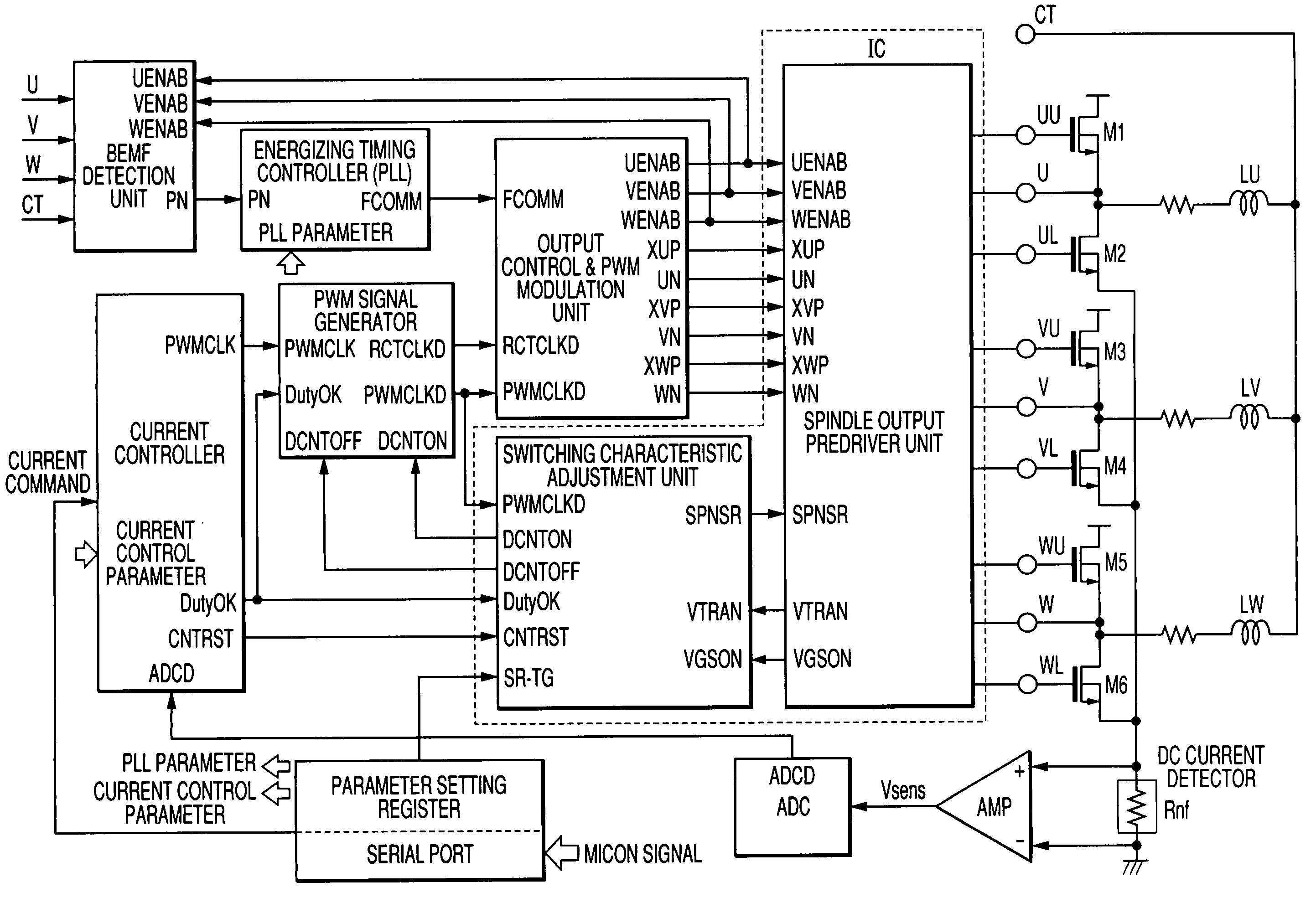
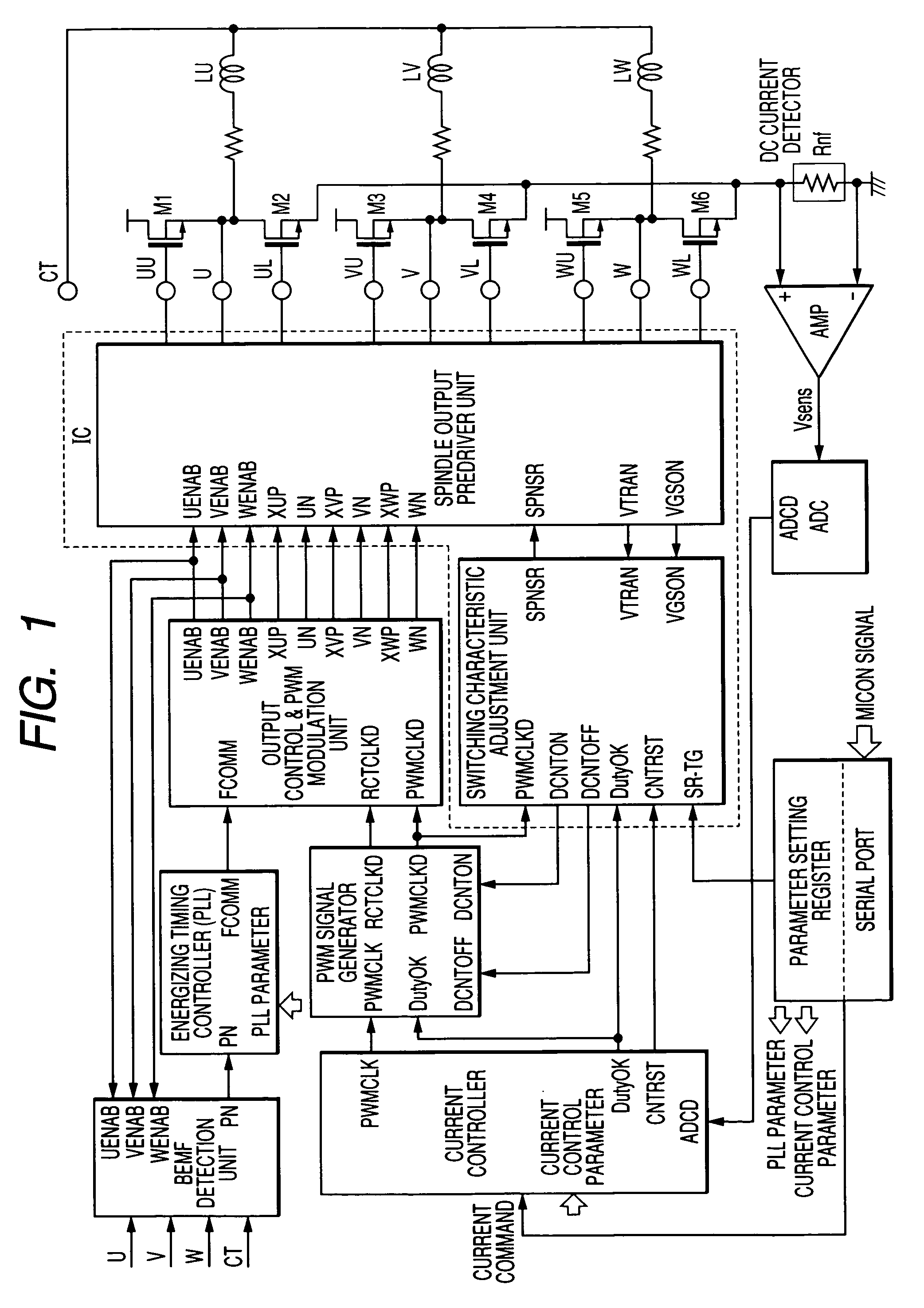
[0030]A block diagram showing one embodiment of a motor drive device according to the present invention is shown in FIG. 1. Three-phase motor coils LU, LV and LW are PWM-driven by power MOSFETs M1 through M6 and a spindle output predriver unit. The spindle output predriver unit is operated with, as inputs, output control signals XUP, UN, XVP, VN, XWP and WN generated by an output control & PWM modulation unit. Also the predriver unit is operated with a current corresponding to an SPNSR signal formed at a switching characteristic adjustment unit and is capable of performing switching or adjustment to switching times.

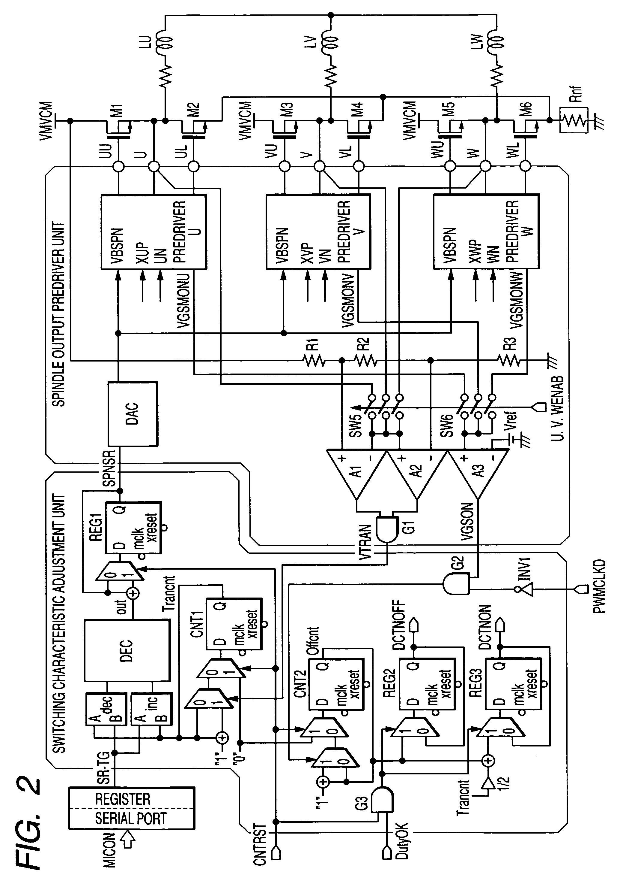
[0031]The spindle output predriver unit is inputted with UENAB, VENAB and WENAB signals. The spindle output predriver unit forms a signal VTRAN having determined the time during which the output of a phase at which a PWM operation is being performed, is being transitioned, and a signal VGSON having determined the time during which each downside power MOSFET is on, and tra...


PUM

PropertyMeasurementUnit
threshold voltageaaaaaaaaaa
currentaaaaaaaaaa
voltagesaaaaaaaaaa

Abstract

A motor drive device which controls a spindle output predriver unit and power MOSFETs of an output stage associated with it to form a PWM signal in such a manner that a detection current formed by a DC shunt resistor and a sense amplifier and a current instruction signal coincide with each other, generates a regenerative signal obtained by giving dead times to the PWM signal, generates an energizing timing signal from the result of BEMF (back electromotive voltage) zero cross detection and generates signals for controlling on / off of power MOSFETs of three phases to thereby drive a three-phase motor, is provided with a switching characteristic adjustment unit which measures a time at which the spindle output is being transitioned and performs such feedback control that the measured time and a designated switching time coincide with each other.

Description

CROSS-REFERENCE TO RELATED APPLICATION[0001]The present application claims priority from Japanese patent application Nos. 2004-050646 filed on Feb. 26, 2004 and 2004-329961 filed on Nov. 15, 2004, the content of which is hereby incorporated by reference into this application.BACKGROUND OF THE INVENTION[0002]The present invention relates to a motor drive device and a motor drive integrated circuit device, and to a technique effective when applied to a rotational control technique of a three-phase spindle motor for HDD (Hard Disk Driver) or the like, for example.[0003]PWM (Pulse Width Modulation) driving has heretofore been adopted in a system for driving a spindle motor for an HDD device. In the case of the PWM driving, power consumed or used up by a transistor to be driven can greatly be reduced. However, there may be cases where noise occurs since an output voltage is transitioned between a power supply and GND at high speed, and an error rate of the HDD device is degraded. When a ...

Claims


Application Information

Patent Timeline
Patent Type & Authority Patents(United States)
IPC IPC(8): G11B15/46G11B15/00H02P6/08H02P6/06H02P6/28H02P7/06
CPCH02P6/002H02P6/28
Inventor KUROSAWA, MINORUKOKAMI, YASUHIKO
Owner RENESAS TECH CORP
Why Eureka
Try Eureka