
Autonomous control method for small unmanned helicopter

a technology of unmanned helicopters and autonomous control systems, which is applied in adaptive control, remote control toys, instruments, etc., can solve the problems of limiting the range over which the helicopter can be deployed, the helicopter cannot be easily carried, and the helicopter cannot be adequately flung, so as to achieve the effect of easy portability and broadening the application of such helicopters

Inactive Publication Date: 2006-03-23
NONAMI KENZO +4
View PDF1 Cites 37 Cited by
  • Summary
  • Abstract
  • Description
  • Claims
  • Application Information

AI Technical Summary

Benefits of technology

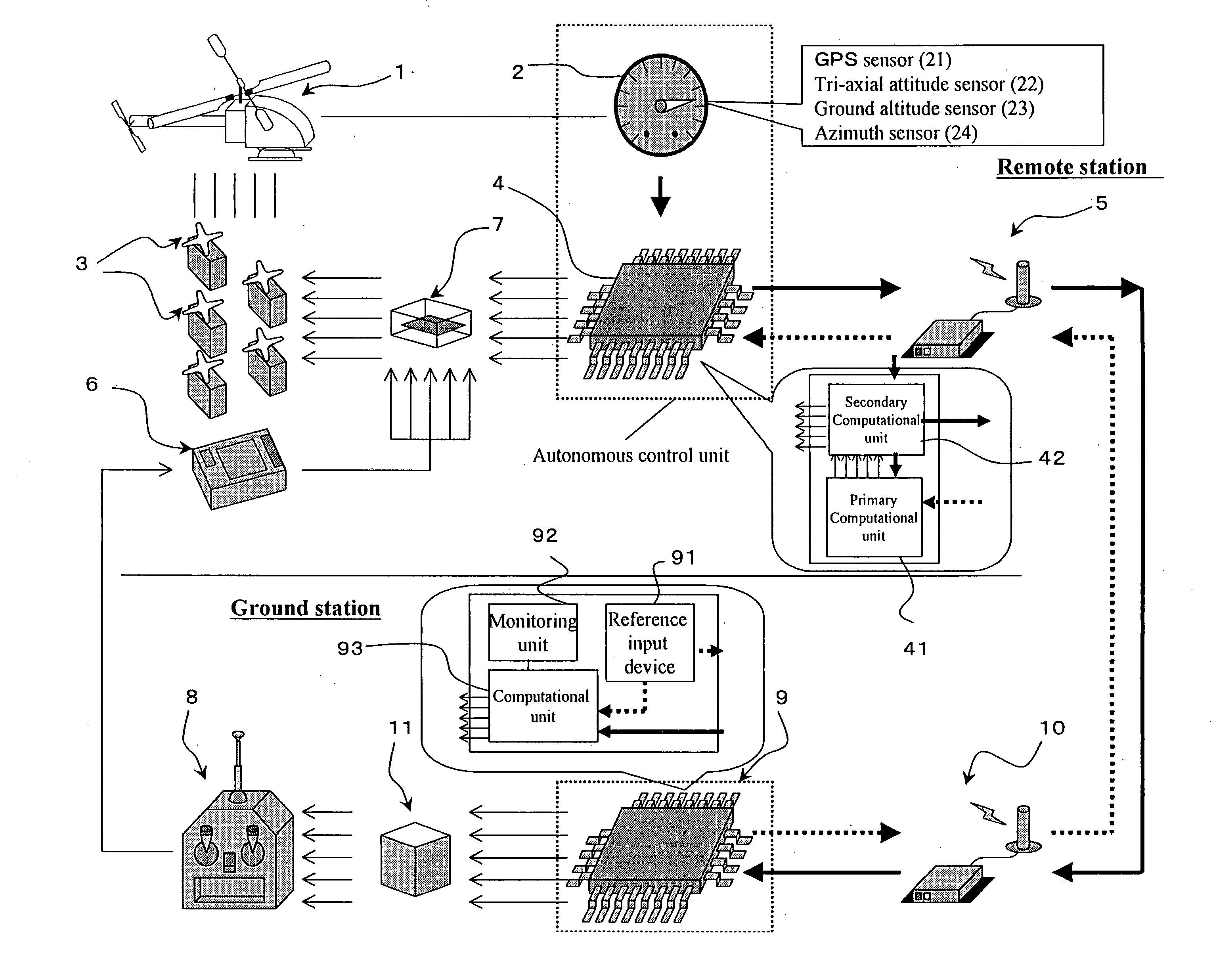
[0054] The autonomous control method of the present invention permits the autonomous control of small unmanned helicopters according to position and velocity target values that are set by the human operator. In addition to implementing an autonomous control unit by mounting the autonomous control device used in this method on the body of a helicopter, we have developed a servo pulse mixing / switching unit that either mixes or switches autonomous control signals and manual operation signals, a pulse generator unit that converts these signals into pulse signals that the manual operation signal transmitter can accept, and an autonomous control algorithm that is well suited for the autonomous control of small unmanned helicopters; as a result, small unmanned helicopters, in the same class as hobby-oriented small radio-controlled helicopters, can be autonomously controlled according to target values. This permits complete autonomous control with hobby-oriented small radio-controlled helicopters; consequently, such helicopters become easily portable and can be adapted to small spaces in which it is impossible to perform operations using the conventional unmanned helicopter, and in which it is difficult to perform manned operations, and in this manner, the application of such helicopters can be broadened.

Problems solved by technology

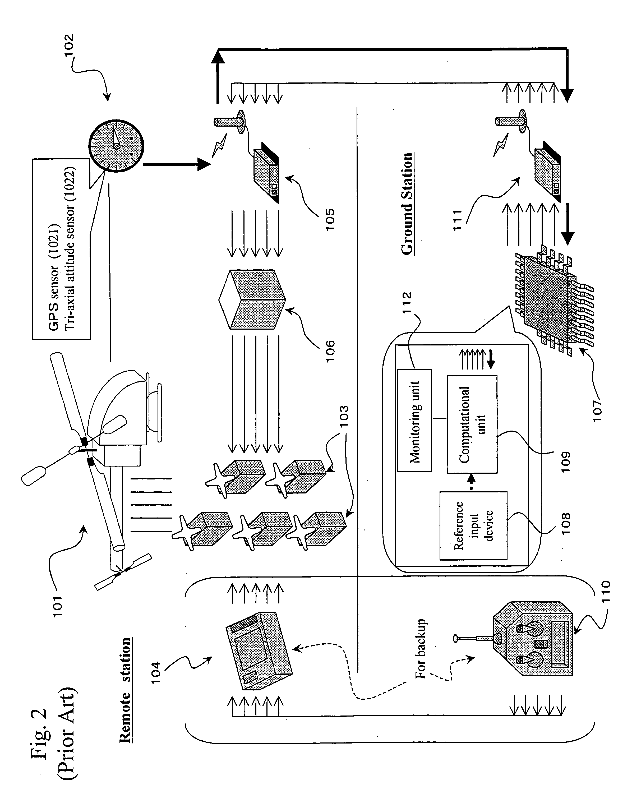
Although the aforementioned sensors and computational unit for the aforementioned conventional autonomous control system are large and heavy, the helicopter can adequately fly even when carrying these items.
However, the unloaded helicopter used in the aforementioned conventional autonomous control system weights approximately 60 kg empty, and approximately 90 kg when fully loaded.
Therefore, such a helicopter cannot easily be carried.
In addition, in order to use the system, the helicopter must have a flight range sufficiently larger than the actual helicopter, which limits the range over which the helicopter can be deployed.
In some cases, manned helicopter operations involve a narrow space in which the aforementioned conventional helicopter cannot negotiate.
Although the above problem can be solved by effecting autonomous control in such a helicopter, the smaller the weight of a helicopter, the more difficult it is to control.
In other words, the autonomous control system is subject to stringent constraints in terms of size and weight, and small helicopters tend to be unstable in terms of dynamic properties.
Therefore, with the aforementioned conventional autonomous control system, it is impossible to mount the autonomous control system on the aforementioned small unmanned helicopter as is.
Further, applying the autonomous control algorithms for the aforementioned conventional autonomous control system to the aforementioned small unmanned helicopter as is does not guarantee adequate control performance.
Further, the calculation of a control instruction value is a time-consuming process due to a large number of computational steps involved in the determination of servo motor control instruction values; consequently, when one attempts to achieve size reductions in the autonomous control system, one must contend with the conflicting requirements of accommodating a large number of computational steps and the stringent constraints imposed on the capabilities of the computational equipment and the size of the control program.
Further, beyond the computational equipment, the sensors are also subject to stringent constraints on size and weight, which clearly adds to the difficulty of construction of small and lightweight autonomous control systems.
However, the process of designing an autonomous control algorithm may require the measurement of manual operation signals.
In such a case, however, characterization input by itself can cause a substantial tilt in the attitude of the aforementioned small unmanned helicopter and sudden acceleration, with a potential risk of accidents.
However, the dynamic characteristics of a helicopter are subject to a complex interplay of dynamical action and fluid dynamic action, which makes analysis an extremely difficult task.
In addition, there have been no reports on the dynamic characteristics of the aforementioned servo motors.
Even if a mathematical model that describes the dynamic characteristics of the aforementioned small unmanned helicopter in detail exists, if the mathematical model is a highly complex one, the development of an autonomous control algorithm will also be difficult.
Autonomous control algorithms that are developed and based on complex mathematical models are generally complex, and may not necessarily be appropriate for execution by a computer that is subject to stringent restrictions on its computational capabilities due to weight limitations.
However, entering such signals into the aforementioned small unmanned helicopter involves a risk.

Method used


Image

  • Autonomous control method for small unmanned helicopter
  • Autonomous control method for small unmanned helicopter
  • Autonomous control method for small unmanned helicopter

Examples


Embodiment Construction

[0074] The inventor of the present invention has consistently pursued autonomous control research from the design of the requisite hardware through the development of autonomous control algorithms. The inventor developed the aforementioned autonomous control system, the aforementioned radio-controlled pulse generator, the hardware for the aforementioned servo pulse mixing / switching unit, and the software on a novel and independent basis. In addition, the inventor conducted flight experiments for the characterization of the aforementioned mathematical models, derived mathematical models from the experimental results, and developed autonomous control algorithms for the small unmanned helicopter using the mathematical models. By using the autonomous control system, the inventor successfully achieved the complete autonomous control of a small helicopter body, with an unloaded weight of approximately 9 kg, according to target values.

[0075] In what follows, we provide a logical explanati...


PUM


Abstract

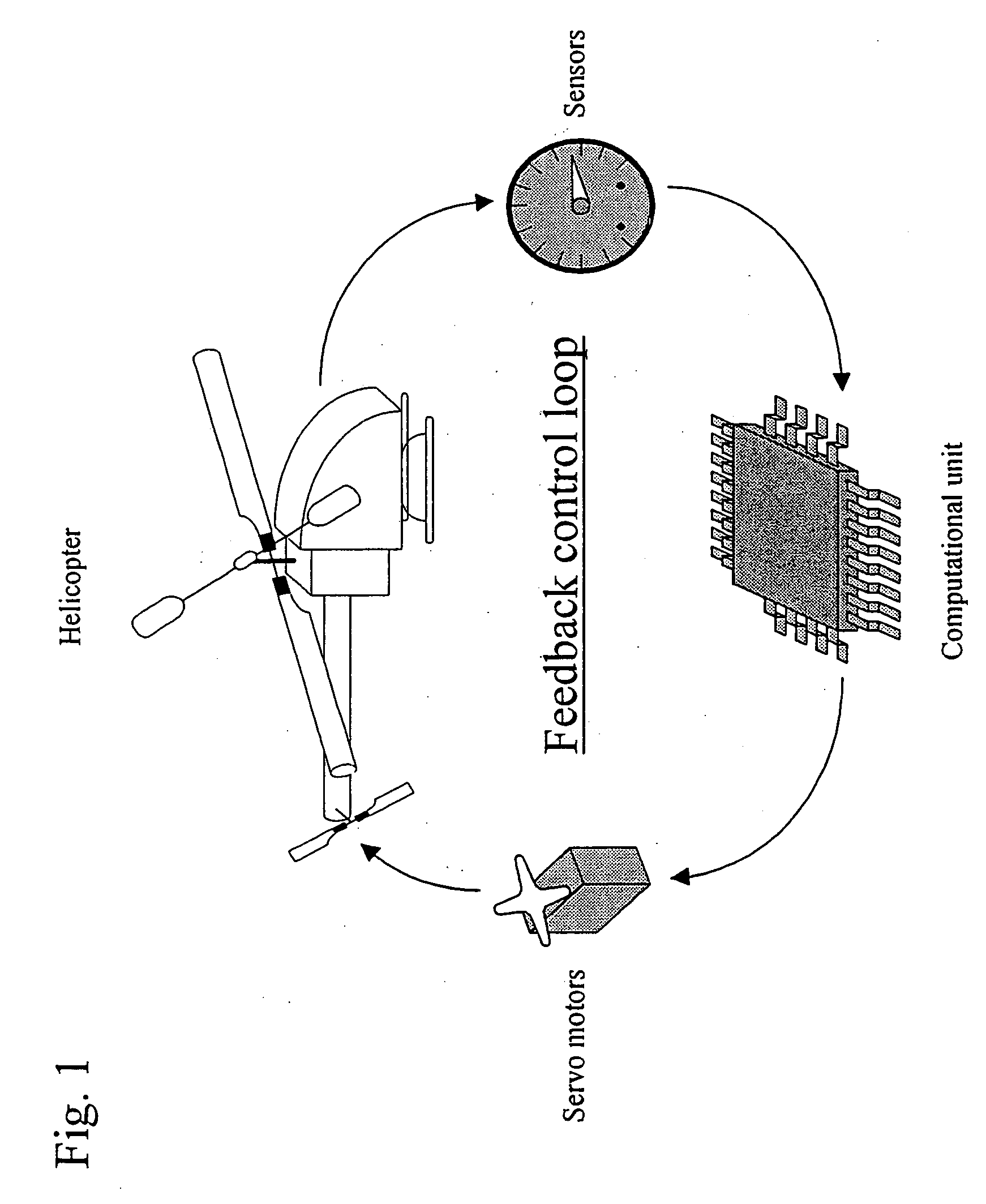
An objective of the present invention is to provide an autonomous control method that autonomously controls a small unmanned helicopter toward target values, such as a set position and velocity, by deriving model formulas that are well suited for the autonomous control of small unmanned helicopters, by designing an autonomous control algorithm based on the model formulas, and by calculating the autonomous control algorithm. The autonomous control system for a small unmanned helicopter of the present invention comprises: sensors that detect the current position, the attitude angle, the altitude relative to the ground, and the absolute azimuth of the nose of the aforementioned small unmanned helicopter; a primary computational unit that calculates optimal control reference values for driving the servo motors that move five rudders on the helicopter from target position or velocity values that are set by the ground station and the aforementioned current position and attitude angle of the small unmanned helicopter that are detected by the aforementioned sensors; an autonomous control system equipped with a secondary computational unit that converts the data collected by said sensors and the computational results as numeric values that are output by said primary computational unit into pulse signals that can be accepted by the servo motors, such that these components are assembled into a small frame box, thereby achieving both size and weight reductions; a ground station host computer that can also be used as the aforementioned computational unit for the aforementioned autonomous control system; if the aforementioned ground station host computer is used as the aforementioned computational unit for the aforementioned autonomous control system, in the process of directing the computational results that are output from said ground station host computer to said servo motors through a manual operation transmitter, a radio control generator that converts said computational results as numerical values into pulse signals that said manual operation transmitter can accept; a servo pulse mixing / switching apparatus, on all said servo motors for said small unmanned helicopter, that permits the switching of manual operation signals and said control signals that are output from said autonomous control system or mixing thereof in any ratio; an autonomous control algorithm wherein the mathematical model for transfer function representation encompassing pitching operation input through pitch axis attitude angles in the tri-axis orientation control for said small unmanned helicopter is defined as Gθ⁡(s)=e-Ls⁢Kθ⁢ωns2(s2+2⁢s⁢ωn⁢ ⁢s⁢s+ωn⁢ ⁢s2)⁢(Tθ⁢s+1)⁢swherein Gθ: parameter e−Ls: dead time element Kθ: model gain Tθ: model gain ωns: natural frequency s: laplace operator ξs: damped ratio such that the aforementioned small unmanned helicopter is controlled autonomously based on the aforementioned mathematical model.

Description

BACKGROUND OF THE INVENTION [0001] 1. Field of the Invention [0002] This invention relates to an autonomous control system for small unmanned helicopters, and autonomous control algorithms that control the rudders for said small unmanned helicopter based on the aforementioned mathematical models. [0003] 2. Description of the Prior Art [0004] Helicopters are flying bodies that have operating ranges such as longitudinal motions, lateral motions, vertical motions, and hovering, which are not exhibited by an aircraft; as such, they have the advantage of being able to flexibly respond to various situations. Based on this advantage, there are hopes for constructing unmanned, small helicopters for use in places that are difficult or dangerous for manned operations, for example, in high-altitude work, such as the inspection of power transmission lines, or in emergency rescue operations or the detection of land mines. Previously, an autonomous control system using an unmanned helicopter for ...

Claims


Application Information

Patent Timeline
IPC IPC(8): B64C27/54B64C13/20A63H30/04B64C39/02G05B13/04G05D1/00G05D1/08G05D1/10G05D1/12
CPCA63H27/12A63H30/04G05D1/102G05D1/0866G05D1/0033G05D1/0858
Inventor NONAMI, KENZOSHIN, JIN OKFUJIWARA, DAIGOHAZAWA, KENSAKUMATSUSAKA, KEITARO
Owner NONAMI KENZO
Learn More