Data reproducing apparatus
a data and apparatus technology, applied in the field of data reproducing apparatuses, can solve problems such as data reproduction abandonment, and achieve the effect of reducing the number of retry times of data reproduction
- Summary
- Abstract
- Description
- Claims
- Application Information
AI Technical Summary
Benefits of technology
Problems solved by technology
Method used
Image
Examples
first embodiment
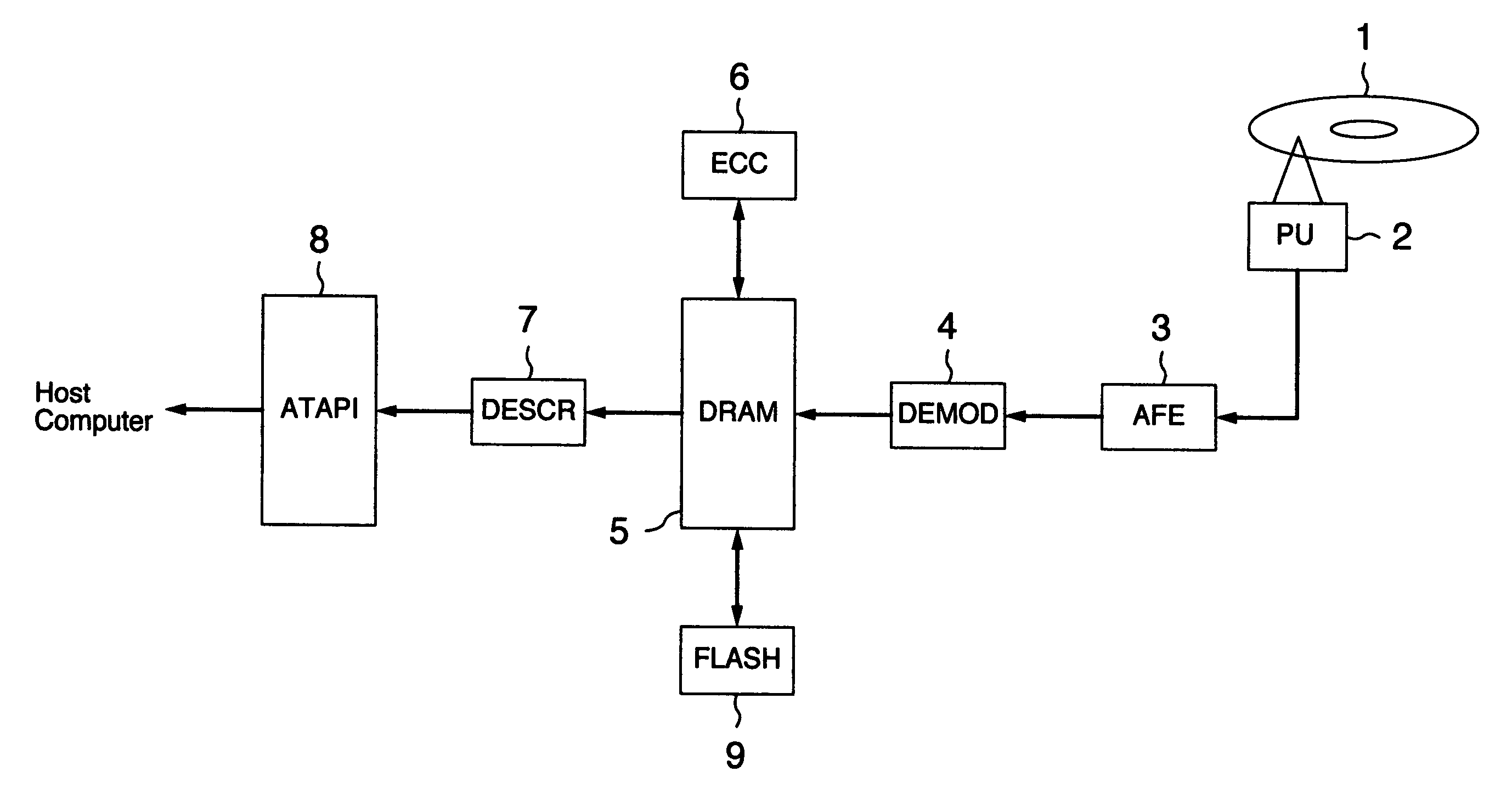
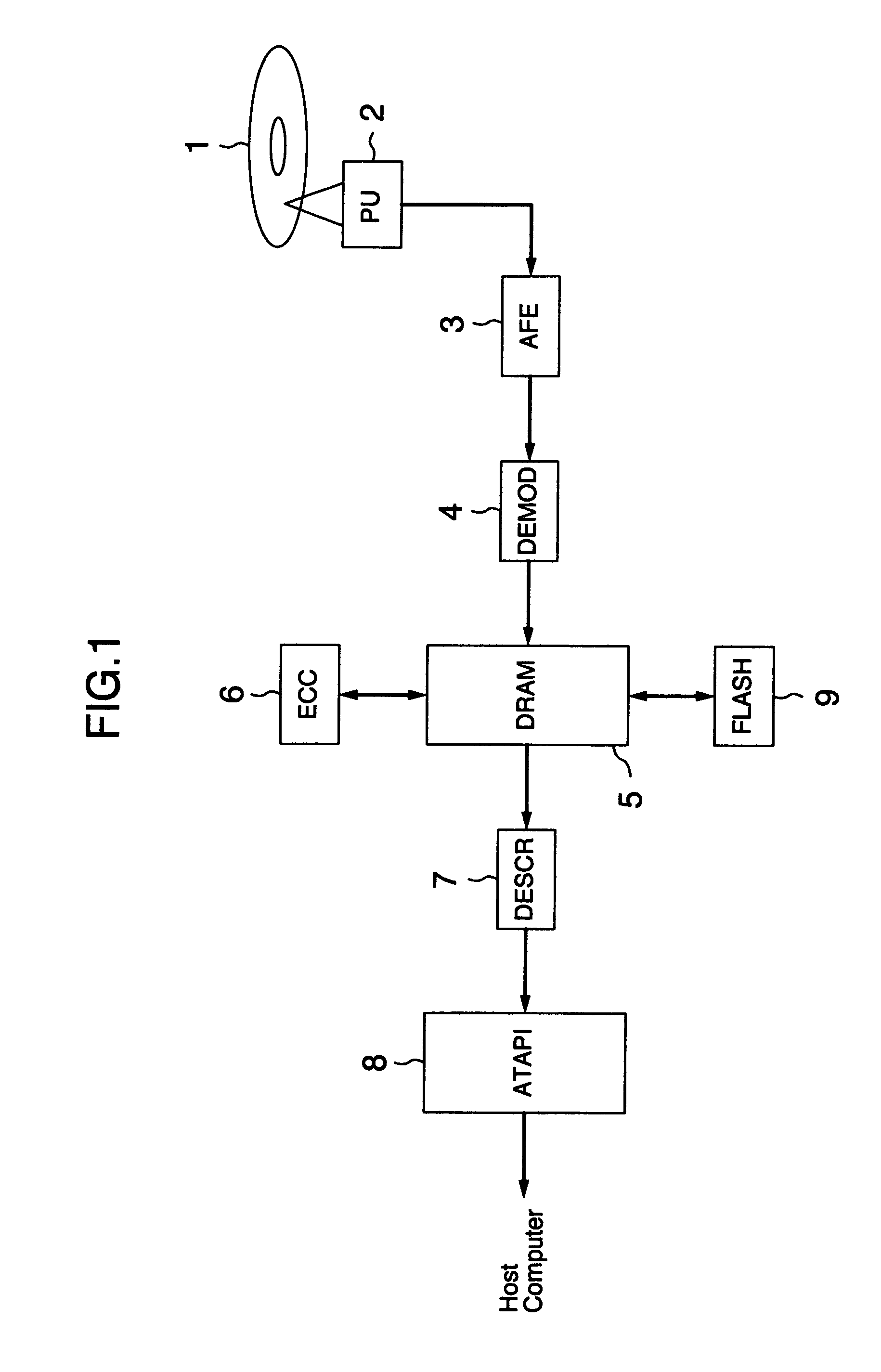
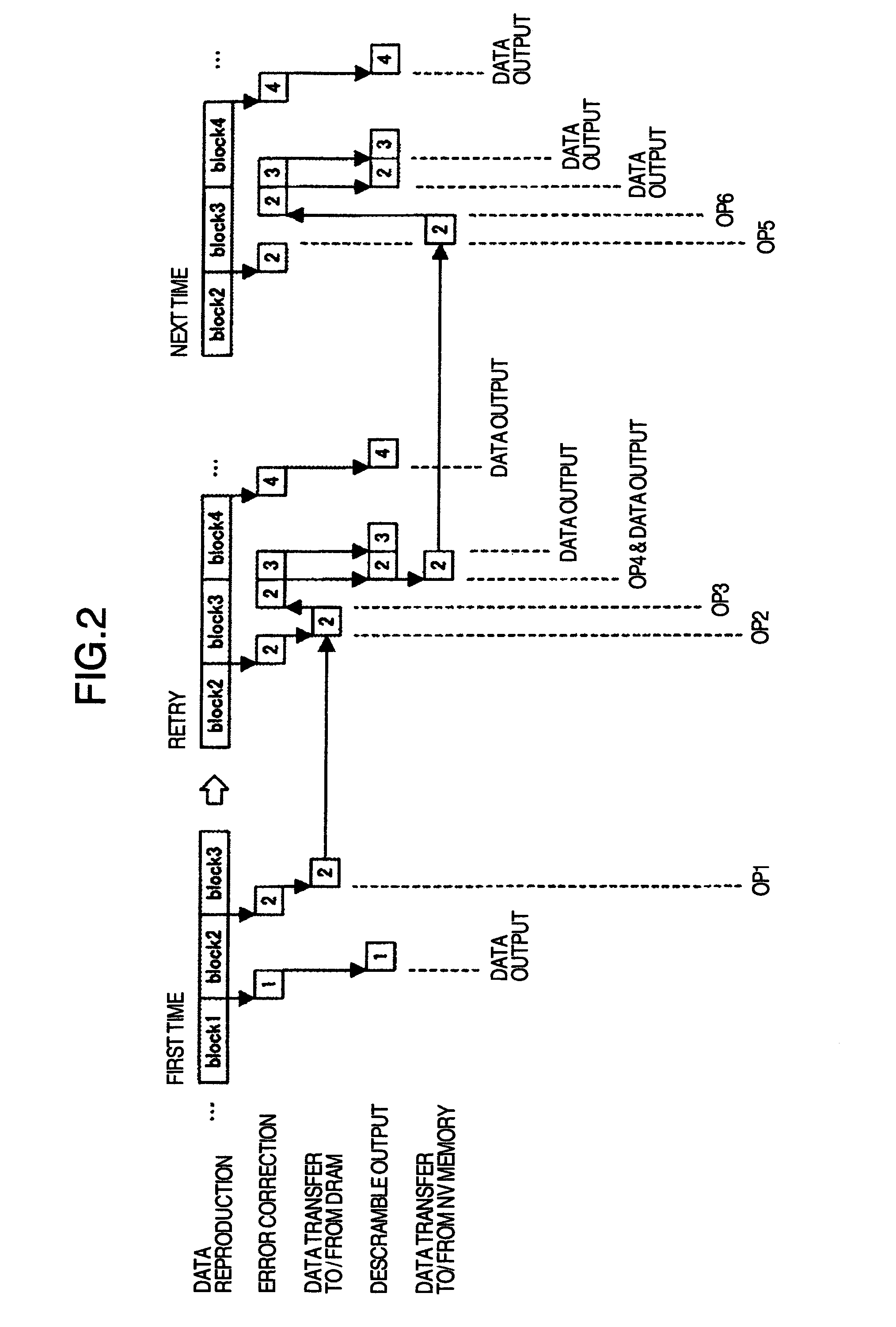
[0020]FIG. 1 is a block diagram showing the structure of a DVD reproducing apparatus according to the present invention. A reproduction signal read from an optical disc 1 via an optical pickup 2 is sent to an analog front end (AFE) 3 which amplifies the reproduction signal and outputs the amplified reproduction signal to a demodulator circuit 4. The demodulator circuit 4 binarizes and 8 / 16-demodulates the input signal, and writes the resultant signal in a DRAM 5 which is used as an error correction memory and a buffer memory. An error correction circuit 6 reads data from DRAM 5, executes an error correction process and writes the resultant data in DRAM 5. A descramble circuit 7 descrambles the data whose error correction was completed, and sends the resultant data to an ATAPI circuit 8 which sends the data supplied from the descramble circuit 7 to a host computer. A nonvolatile memory 9 stores the data and addresses whose error correction was completed. The data stored in the nonvol...
second embodiment
[0037]FIG. 4 is a block diagram showing the structure of a DVD reproducing apparatus according to the present invention. Description of identical parts to those shown in FIG. 1 is omitted. A signal read from a recordable optical disc 11 via an optical pickup 12 is sent to an AFE 3. An 8 / 16 modulation signal sent from a modulation circuit 14 is recorded in the optical disc 11. The modulation circuit 14 8 / 16-modulates data and error correction codes sent from a DRAM 15 and sends the resultant data to the optical pickup 12. DRAM 15 is used as an error correction memory and a buffer memory.
[0038]When data is reproduced from DVD, a reproduction signal read from the optical disk 11 via the optical pickup 12 is first amplified at AFE 3, and then the demodulator circuit 4 binarizes and 8 / 16-demodulates the input signal and stores the resultant data in DRAM 15. Next, the error correction circuit 6 corrects errors of the data stored in DRAM 15. The data after error correction completion is se...
third embodiment
[0045]FIG. 5 is a block diagram showing the structure of a DVD reproducing apparatus according to the present invention. Description of identical parts to those shown in FIGS. 1 and 4 is omitted.
[0046]When data is reproduced from DVD, a reproduction signal read from an optical disc 11 via an optical pickup 12 is first amplified at an AFE 3, and then a demodulator circuit 4 binarizes and 8 / 16-demodulates the input signal and stores the resultant data in a DRAM 15. Next, an error correction circuit 6 corrects errors of the data stored in DRAM 15. The data after error correction completion is sent to a descramble circuit 7 whereat descramble is performed, and the resultant data is output to a host computer via an ATAPI circuit 8.
[0047]If data error is uncorrected at the error correction circuit 6, data and error correction codes other than uncorrected data in the corresponding block are all copied to a different area of DRAM 15. Retry is performed and if data error is uncorrected again...
PUM
 Abstract
Description
Claims
Application Information
 - R&D
- Intellectual Property
- Life Sciences
- Materials
- Tech Scout
- Unparalleled Data Quality
- Higher Quality Content
- 60% Fewer Hallucinations
Browse by: Latest US Patents, China's latest patents, Technical Efficacy Thesaurus, Application Domain, Technology Topic, Popular Technical Reports.
© 2025 PatSnap. All rights reserved.Legal|Privacy policy|Modern Slavery Act Transparency Statement|Sitemap|About US| Contact US: help@patsnap.com


