
Delay circuit for low power ring oscillator

a delay circuit and low-power technology, applied in the direction of pulse generation by logic circuits, pulse automatic control, pulse technique, etc., can solve the problems of zigbee chip manufacturing cost increase, ring oscillator, high phase noise, etc., and achieve the effect of reducing the current consumption of the delay circui

Inactive Publication Date: 2012-05-29
SAMSUNG ELECTRO MECHANICS CO LTD
View PDF3 Cites 6 Cited by
  • Summary
  • Abstract
  • Description
  • Claims
  • Application Information

AI Technical Summary

Benefits of technology

The solution effectively reduces current consumption, minimizes phase noise, and allows for control of operation frequency across various ranges without the use of inductors, making it suitable for implementation in a narrow chip area.

Problems solved by technology

The inductor, therefore, is almost the size of a chip, such that the manufacturing cost of a Zigbee chip is increased.
However, the ring oscillator has disadvantages such as high phase noise, a narrow frequency range, and large current consumption, as compared to the known LC oscillator.

Method used


Image

  • Delay circuit for low power ring oscillator
  • Delay circuit for low power ring oscillator
  • Delay circuit for low power ring oscillator

Examples


Embodiment Construction

[0027]Hereinafter, exemplary embodiments of the present invention will be described with reference to the accompanying drawings. However, the exemplary embodiments are described by way of examples only and the present invention is not limited thereto.

[0028]In describing the present invention, if a detailed description of well-known technology relating to the present invention may unnecessarily make unclear the spirit of the present invention, a detailed description thereof will be omitted. Further, the following terminologies are defined in consideration of the functions in the present invention and may be construed in different ways by the intention of users and operators. Therefore, the definitions thereof should be construed based on the contents throughout the specification.

[0029]As a result, the spirit of the present invention is determined by the claims and the following exemplary embodiments may be provided to efficiently describe the spirit of the present invention to those ...


PUM


Abstract

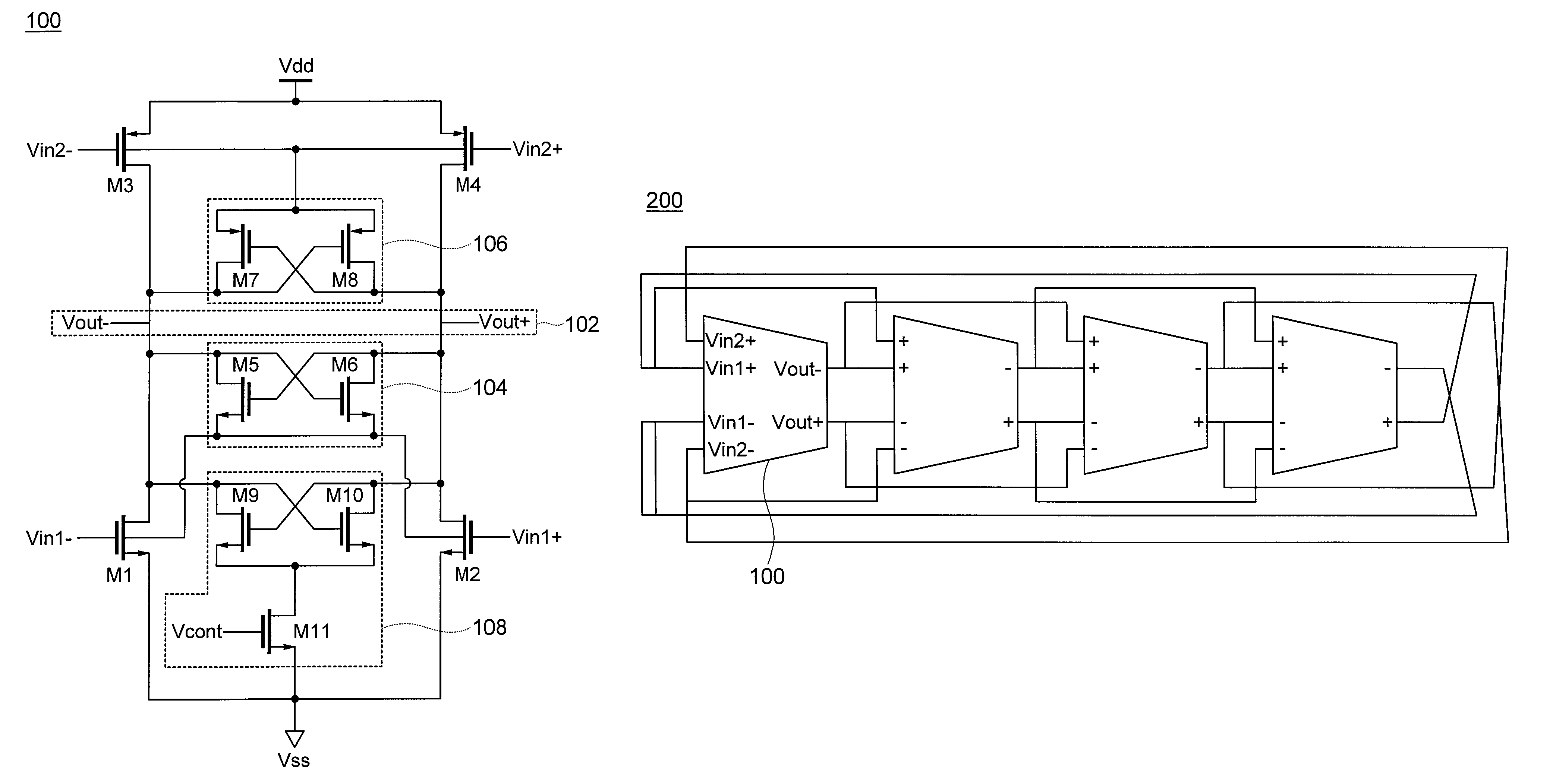
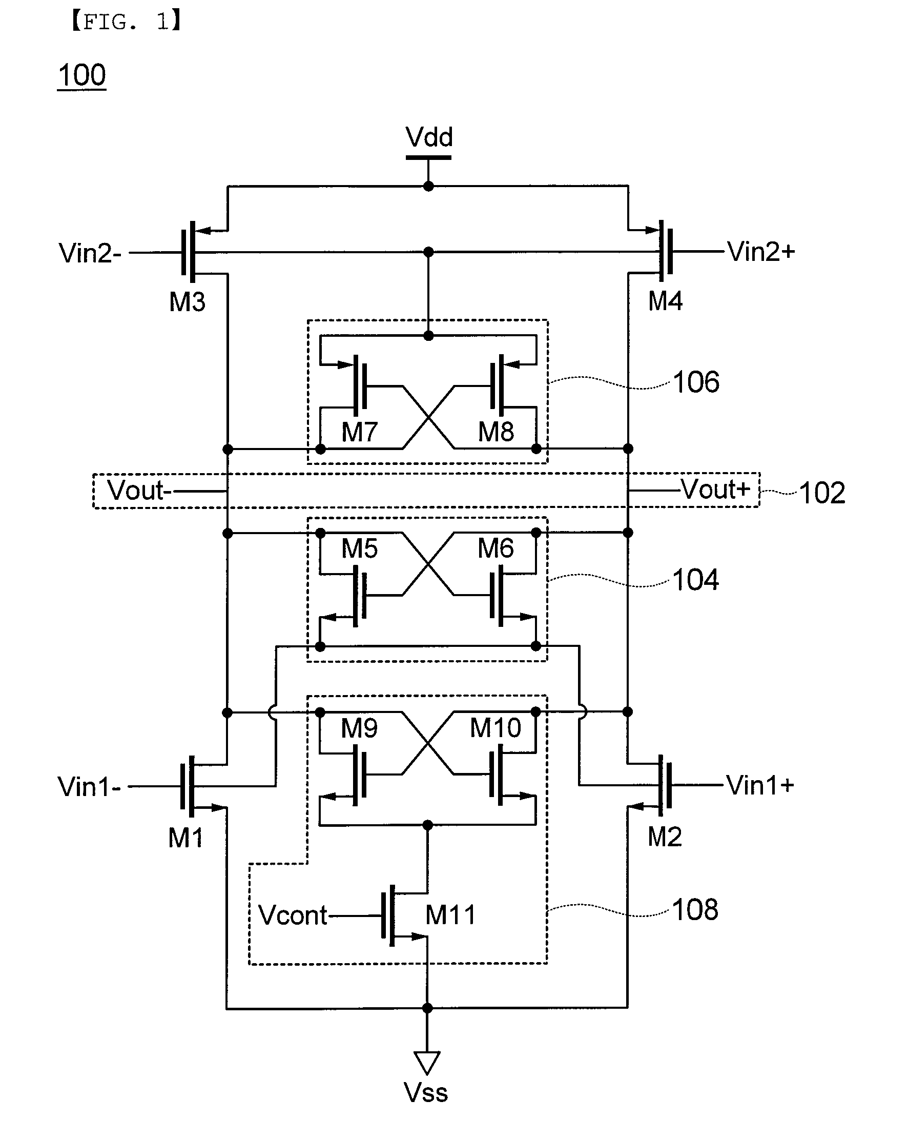
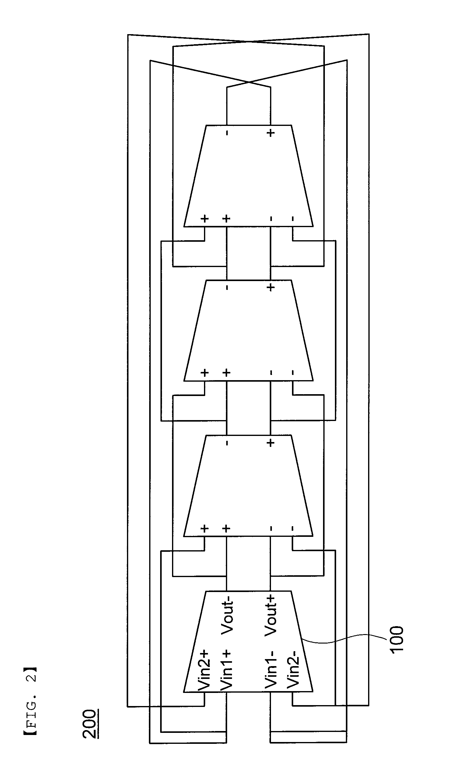
Disclosed herein is a delay circuit for a low power ring oscillator. The delay circuit includes: a pair of N type transistors that receive first differential input signals Vin1+ and Vin1−; a pair of P type transistors that receive second differential input signals Vin2+ and Vin2−; a differential output terminal that outputs differential output signals Vout+ and Vout− generated from the pair of N type transistors and the pair of P type transistors; an N type detector that supplies a body voltage to the pair of N type transistors; and a P type detector that supplies a body voltage to the pair of P type transistors.

Description

CROSS REFERENCE TO RELATED APPLICATION[0001]This application claims the benefit of Korean Patent Application No. 10-2010-0057583, filed on Jun. 17, 2010, entitled “Delay Circuit For Low Power Ring Oscillator”, which is hereby incorporated by reference in its entirety into this application.BACKGROUND OF THE INVENTION[0002]1. Technical Field[0003]The present invention relates to a delay circuit for a low power ring oscillator, and more particularly, to a technology for improving an operation frequency of a delay circuit while simultaneously minimizing current consumption thereof.[0004]2. Description of the Related Art[0005]Recently, due to the demands for low cost and low power wireless radio, the use of Zigbee technology according to the IEEE 802.15.4 standard has increased. Therefore, solutions using Zigbee have been developed in various fields such as a smart grid power system, a building control, an LED illumination field, and the like.[0006]In addition, the development of a wirel...

Claims


Application Information

Patent Timeline
Patent Type & Authority Patents(United States)
IPC IPC(8): H03K3/03
CPCH03K3/012H03K3/0322
Inventor KIM, MYEUNG SUCHO, HAN JINLIM, JOON HYUNGHONG, KYUNG HEEKWON, YONG IL
Owner SAMSUNG ELECTRO MECHANICS CO LTD
Learn More