Optical component and method for manufacturing the same

a technology of optical components and components, applied in the field of optical components, can solve the problems of compromising heat resistance, compromising adhesion, and difficulty in obtaining anti-reflection films having satisfactory physical properties with these related art techniques, and achieve the effect of preventing performance degradation of optical components

Active Publication Date: 2012-05-29
NIKON ESSILOR
View PDF27 Cites 8 Cited by
  • Summary
  • Abstract
  • Description
  • Claims
  • Application Information

AI Technical Summary

Benefits of technology

[0014]According to some aspects of the invention, performance degradation in optical components can be prevented.

Problems solved by technology

It has been difficult, however, to obtain an antireflection film having satisfactory physical properties with these related art techniques.
For example, a larger film thickness of the antireflection film provides an improved abrasive resistance, but tends to cause a compromised adhesion between the antireflection film and a hard coat, and a compromised heat resistance.
Also, although an increased ratio of the low refractive index layers in the antireflection film provides improved heat resistance, it becomes difficult to provide low reflection properties in a wide area.

Method used


Image

  • Optical component and method for manufacturing the same
  • Optical component and method for manufacturing the same
  • Optical component and method for manufacturing the same

Examples


first embodiment

(First Embodiment)

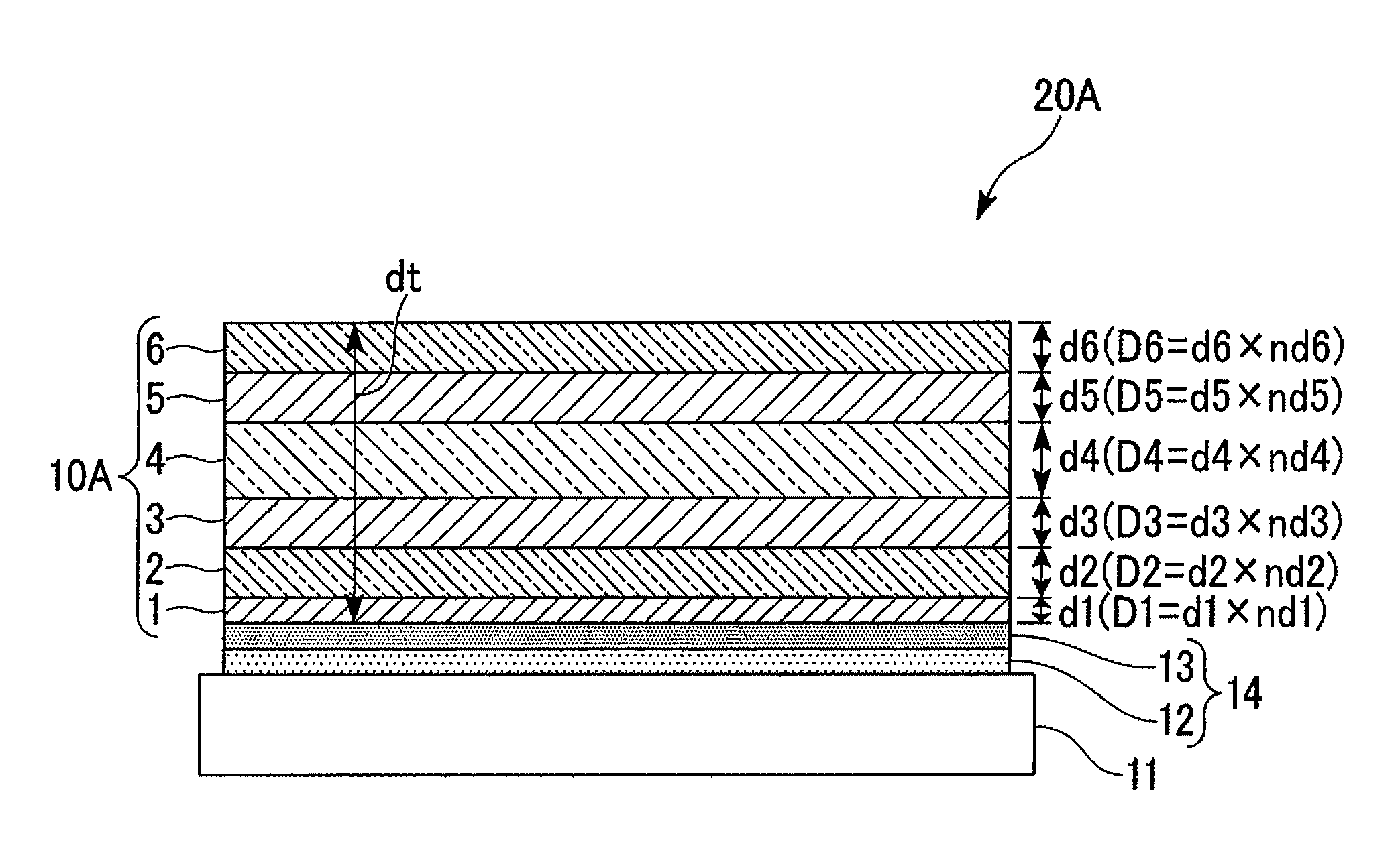
[0024]A first embodiment will be described. FIG. 1 schematically illustrates an exemplary optical component 20A according to the first embodiment. In the present embodiment, the optical component 20A is, for example, a spectacle lens.

[0025]As illustrated in FIG. 1, the optical component 20A includes a plastic substrate 11 and an antireflection film 10A deposited on the substrate 11. In the present embodiment, an intermediate layer 14 is disposed between a surface of the substrate 11 and the antireflection film 10A. In the present embodiment, the intermediate layer 14 includes a primer layer 12 and a hard-coat layer 13.

[0026]In the following description, the layer 14 and the film 10A deposited on the surface of the substrate 11 will be described mainly. In practice, a layer and a film are similar to the layer 14 and the film 10A respectively deposited on the surface are deposited on a back surface of the substrate 11.

[0027]The substrate 11 is illustrated as a planar...

second embodiment

(Second Embodiment)

[0058]Next, a second embodiment will be described. In the following description, components the same as or similar to those of the foregoing embodiment will be denoted by the same reference numerals and description thereof will be simplified or even omitted.

[0059]FIG. 3 schematically illustrates an optical component 20B according to the second embodiment. An antireflection film 10B of the optical component 20B illustrated in FIG. 3 is a multilayer film having eight layers.

[0060]In the present embodiment, the first layer 1, the third layer 3, the fifth layer 5 and the seventh layer 7 are high refractive index layers which is a ZrO2 layer. The second layer 2, the fourth layer 4, the sixth layer 6 and the eighth layer 8 are low refractive index layers which is a SiO2 layer. That is, the first layer 1 of the antireflection film 10B deposited closest to the substrate 11 is a high refractive index layer and the eighth layer 8 of antireflection film 10B deposited furthes...

third embodiment

(Third Embodiment)

[0064]Next, a third embodiment will be described. In the following description, components that are the same as or similar to those of the foregoing embodiment will be denoted by the same reference numerals and description thereof will be simplified or even omitted.

[0065]FIG. 4 schematically illustrates an exemplary optical component 20C according to the third embodiment. As illustrated in FIG. 4, the optical component 20C includes a water-oil-repelling film 9 which covers the antireflection film 10B. A configuration the optical component 20C is the same as that of the optical component 20B according to the second embodiment except that the water-oil-repelling film 9 is provided. The water-oil-repelling film 9 covers the eighth layer 8. The water-oil-repelling film 9 is deposited on an outermost layer of the antireflection film 10B which is deposited furthest from the substrate 11.

[0066]The water-oil-repelling film 9 includes, for example, a fluorine-substituted al...


PUM

PropertyMeasurementUnit
wavelengthaaaaaaaaaa
total physical thickness dtaaaaaaaaaa
refractive indexaaaaaaaaaa

Abstract

An optical component includes an antireflection film that is a multilayer film having alternately-laminated six or more layers including high refractive index layers and low refractive index layers; wherein a first layer of the antireflection film deposited closest to the substrate is a high refractive index layer; λ satisfies 480 nm≦λ≦530 nm where λ is the wavelength of light incident into the antireflection film; an optical thickness D1 of the first layer satisfies 0.02λ≦D1≦0.04λ; an optical thickness Dm of a layer of the antireflection film that is located fifth from an outermost layer deposited furthest from the substrate satisfies 0.19λ≦Dm≦0.75λ; a total physical thickness dt of the entire antireflection film satisfies 350 nm≦dt≦480 nm; and a total physical thickness da of the low refractive index layers satisfies 0.65 dt≦da≦0.80 dt.

Description

CROSS-REFERENCE TO RELATED APPLICATION[0001]This is a Continuation Application of International Application No. PCT / JP2008 / 067431, filed Sep. 26, 2008 which claims priority to Japanese Patent Application No. 2007-254334 filed Sep. 28, 2007. The contents of the aforementioned applications are incorporated herein by reference.BACKGROUND[0002]1. Field of the Invention[0003]The present invention relates to an optical component and a method for manufacturing the same.[0004]2. Description of Related Art[0005]Recently, plastic lenses are often used as spectacle lenses for their advantages in being lightweight, having improved shock resistance, and being easy to color. The plastic lenses used in spectacle lenses typically have antireflection films deposited on both surfaces thereof in order to prevent surface reflection.[0006]Such antireflection films for spectacle lenses are required to have excellent optical properties including low reflection properties (i.e., low reflection properties i...

Claims


Application Information

Patent Timeline
Patent Type & Authority Patents(United States)
IPC IPC(8): G02B1/10G02B1/11G02B1/115G02B1/14G02C7/00G02C7/02
CPCG02B1/111G02B1/115Y10T156/10
Inventor TOMODA, MASAOKI
Owner NIKON ESSILOR
Why Eureka
Try Eureka