Nacelle assembly having inlet bleed

a turbine engine and nacelle technology, applied in the direction of machines/engines, liquid fuel engines, transportation and packaging, etc., can solve the problems of reducing the efficiency of the turbo fan engine during the cruise conditions of the aircraft, and achieve the effect of increasing energy flow

Active Publication Date: 2012-06-05
RTX CORP
View PDF130 Cites 27 Cited by
  • Summary
  • Abstract
  • Description
  • Claims
  • Application Information

AI Technical Summary

Benefits of technology

[0006]The present nacelle assembly for a turbine engine has a cowl. The cowl extends along an axis and has an exterior surface spaced from an interior surface. The interior surface forms an air inlet for directing airflow to the turbine engine. An opening is disposed on the cowl. A device for creating suction through the opening is in fluid communication with the opening. The opening removes a portion of a boundary layer flow through the cowl, thereby providing higher energy flow along the interior surface.

Problems solved by technology

Disadvantageously, the “thick” inlet lip section may reduce the efficiency of the turbo fan engine during cruise conditions of the aircraft, which conditions exist for the large majority of the flight of the aircraft.

Method used


Image

  • Nacelle assembly having inlet bleed
  • Nacelle assembly having inlet bleed
  • Nacelle assembly having inlet bleed

Examples


Embodiment Construction

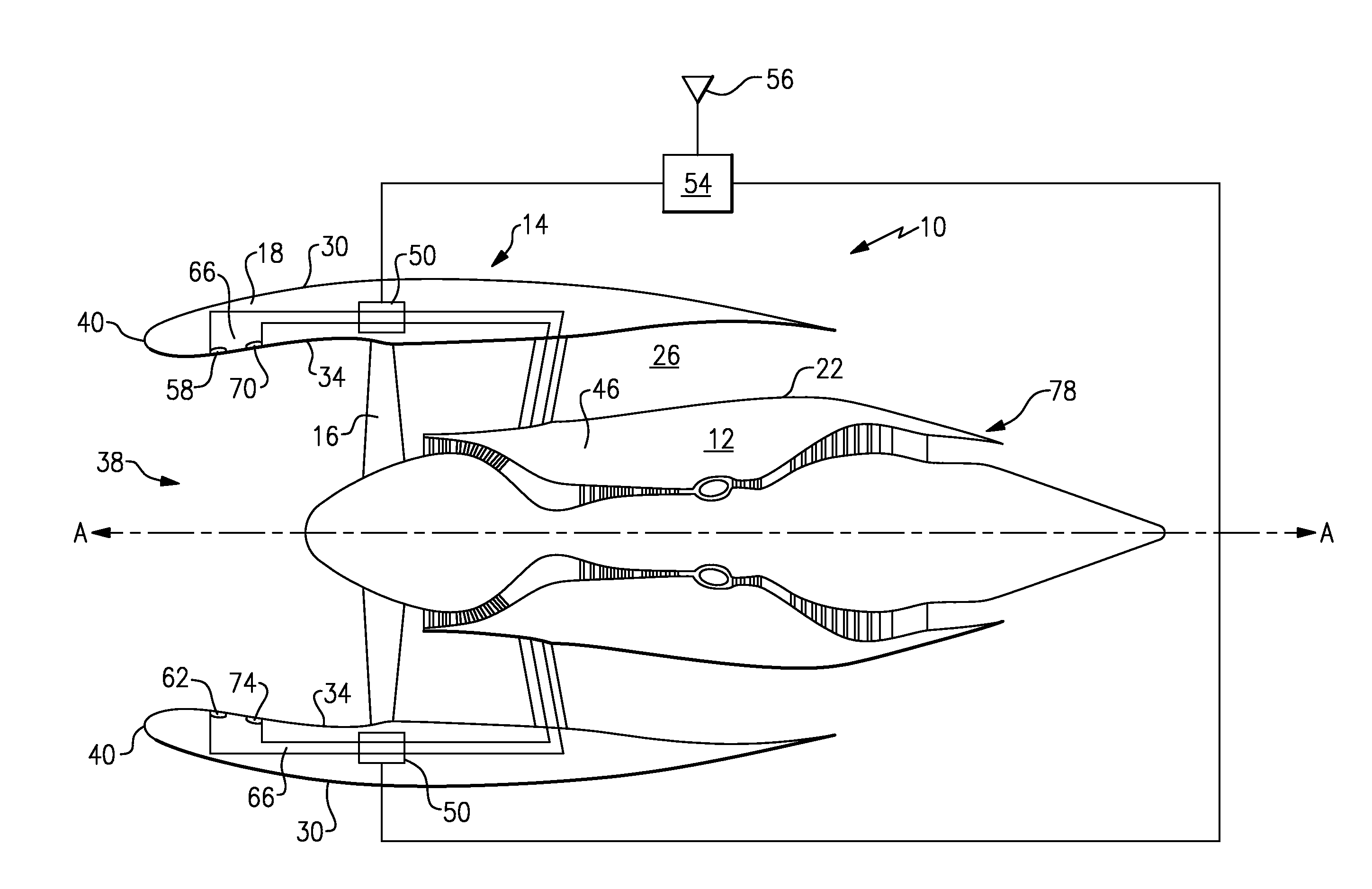
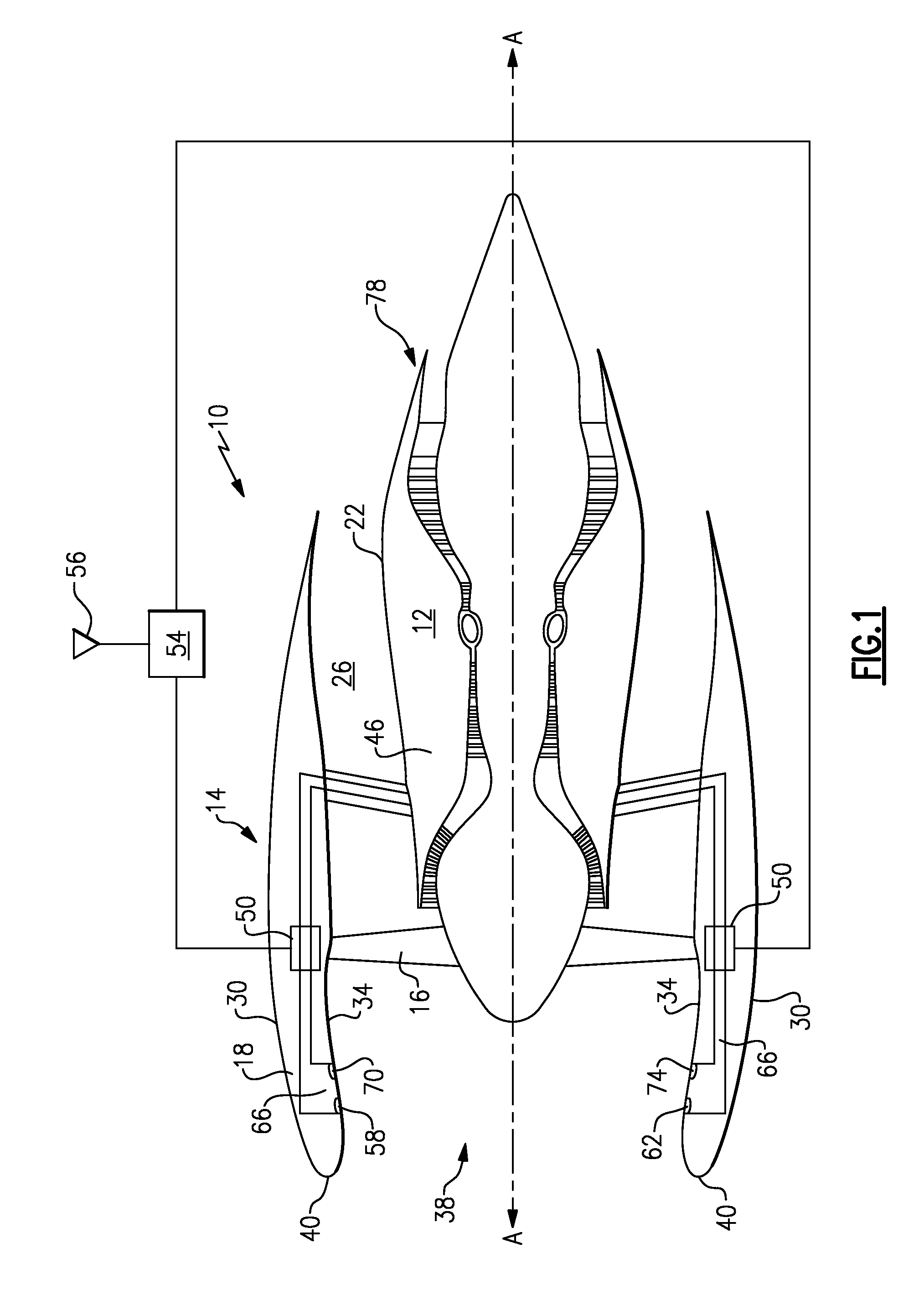
[0013]With reference to FIG. 1, there is shown a cross-sectional view of a turbine engine assembly 10. Part of turbine engine assembly 10 is nacelle assembly 14. Nacelle assembly 14 has fan cowl 18 and is spaced from core cowl 22 of turbine engine 12 to form bypass flow passage 26. Fan 16 is driven by turbine engine 12 and passes primary thrust through bypass flow passage 26 as known.

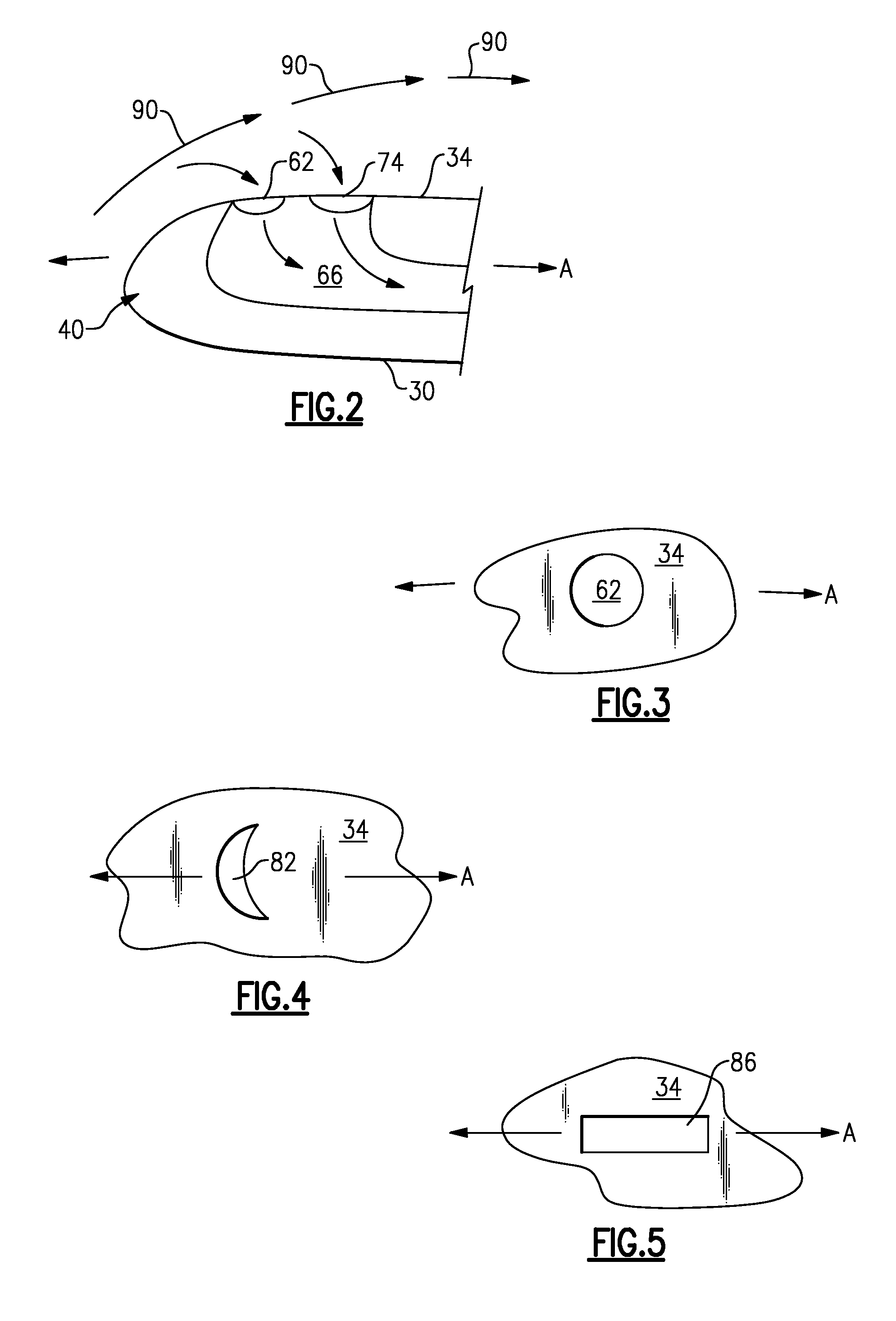
[0014]Nacelle assembly 14 is disposed about axis A and has exterior surface 30 and interior surface 34. Exterior surface 30 and interior surface 34 form lip 40. Interior surface 34 further defines air inlet 38 that provides airflow to turbine engine 12 and fan 16.

[0015]With reference to FIG. 1, nacelle assembly 14 has first opening 58, second opening 62, third opening 70 and fourth opening 74. These openings 58, 62, 70 and 74 are disposed on interior surface 34 of fan cowl 18 as shown and are in fluid communication with flow volume 66. First opening 58 is spaced away from third opening 70 along axis A w...


PUM


Abstract

A nacelle assembly for a turbine engine has a cowl. The cowl extends along an axis and has an exterior surface spaced from an interior surface. The interior surface forms an air inlet for directing airflow to the turbine engine. An opening is disposed on the cowl. A device for creating suction through the opening is in fluid communication with the opening. The opening removes a portion of a boundary layer flow through the cowl, thereby providing higher energy flow along the interior surface.

Description

BACKGROUND OF THE INVENTION[0001]This invention relates to a nacelle assembly for a turbine engine, particularly for an aircraft.[0002]For a gas turbine engine, such as a turbo fan engine, air is pressurized in a compressor and mixed with fuel in a combustor to generate hot combustion gases. These gases flow downstream through the turbine stages of the engine, which extract energy from the gases. In a two spool gas turbine engine, a high pressure turbine powers a high pressure compressor, while a low pressure turbine powers the fan section disposed upstream of the compressor and a low pressure compressor.[0003]Combustion gases are discharged from the turbo fan engine through a core exhaust nozzle while fan air is discharged through an annular fan exhaust nozzle defined at least partially by a nacelle surrounding the core engine. A majority of the propulsion thrust is provided by the pressurized fan air, which is discharged through the fan exhaust nozzle. The remaining thrust is prov...

Claims


Application Information

Patent Timeline
Patent Type & Authority Patents(United States)
IPC IPC(8): F01D13/02
CPCB64D33/02B64D2033/0226B64D2033/0286
Inventor HAAS, MARTIN
Owner RTX CORP
Why Eureka
Try Eureka