Control device for surgical stoma

a control device and stoma technology, applied in non-surgical orthopedic devices, suction devices, medical science, etc., can solve the problems of bursting of collection bags, pain and discomfort of users, and inconvenient and uncomfortable pouching systems for users, etc., to achieve convenient and efficient

Inactive Publication Date: 2012-06-05
SMITH STEPHEN +1
View PDF3 Cites 4 Cited by
  • Summary
  • Abstract
  • Description
  • Claims
  • Application Information

AI Technical Summary

Benefits of technology

[0009]In view of the foregoing disadvantages inherent in the prior art, the general purpose of the present disclosure is to provide a control device for a surgical stoma, to include all the advantages of the prior art and to overcome the drawbacks inherent therein.
[0012]Yet another object of the present disclosure is to provide an easy and efficient way of releasing gases produced in a body of a user having a surgical stoma.
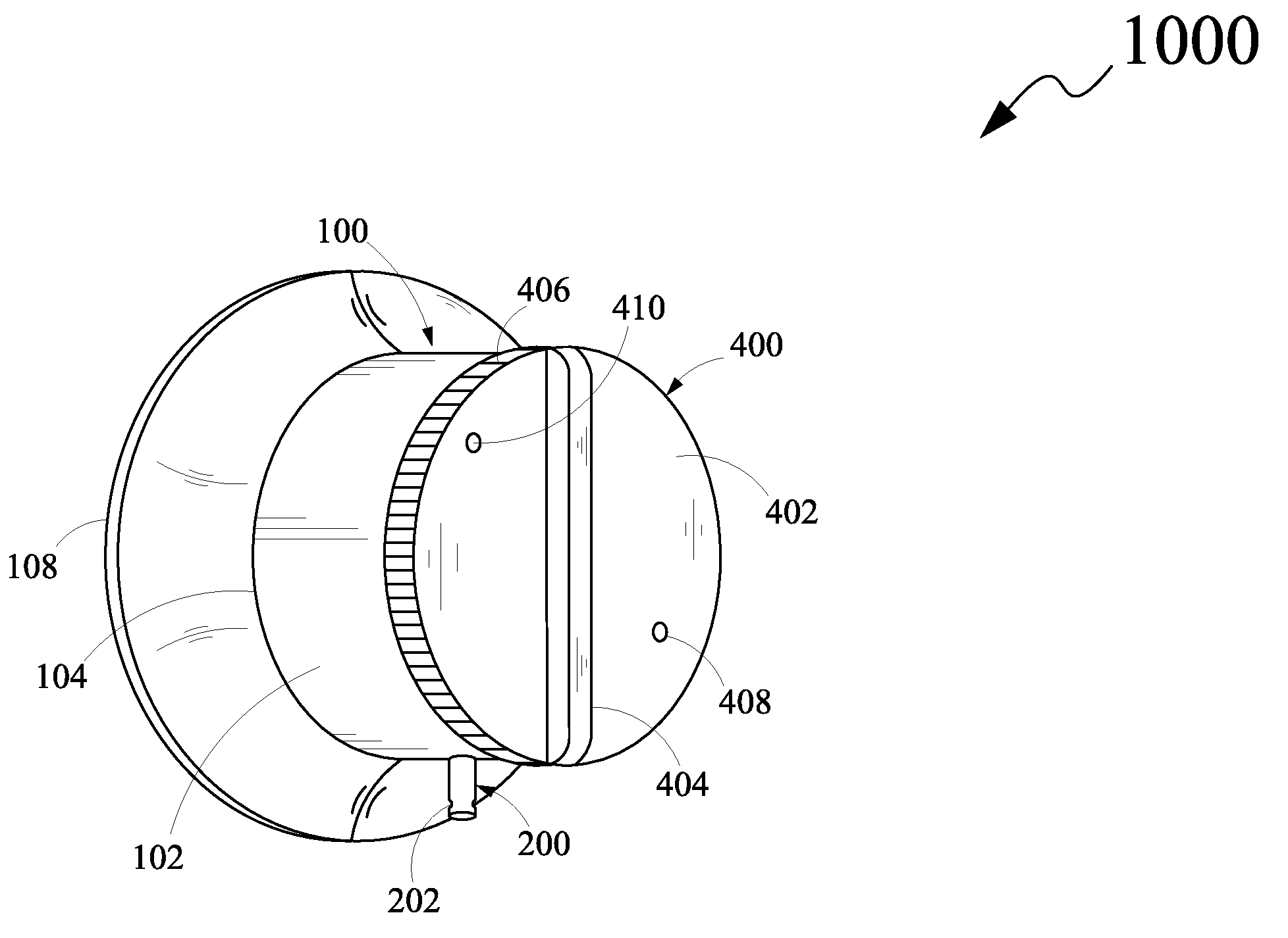
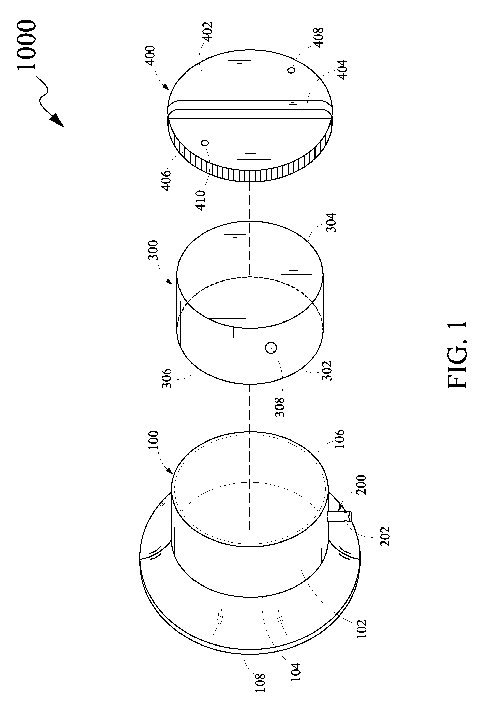
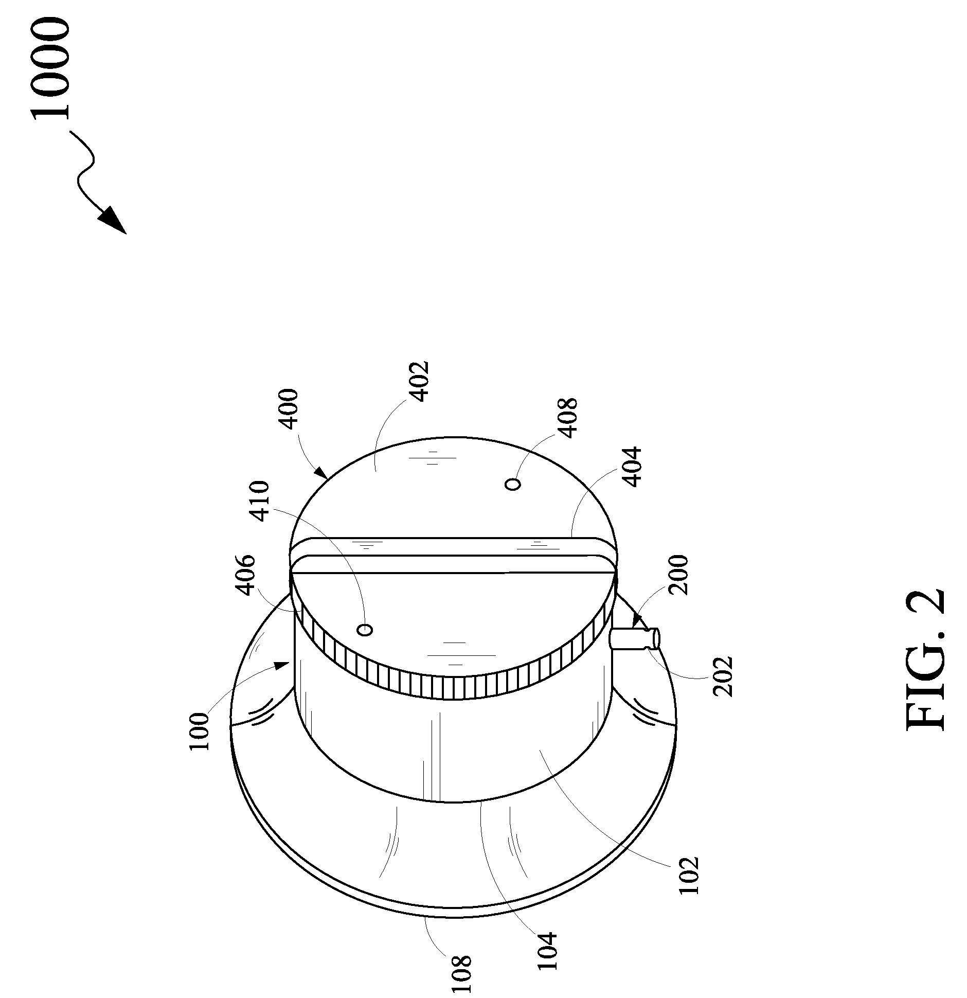
[0013]In light of the above objects, in one aspect of the present disclosure, a control device for a surgical stoma is provided. The control device comprises a first cylindrical hollow body member, a drain tube, a second cylindrical hollow body member and a knob. The first cylindrical hollow body member comprises a first sidewall, a first open end portion and a second open end portion. The first cylindrical hollow body member further comprises a skirt portion extending radially outward from the first open end portion. The skirt portion is capable of being removably attached to a surface surrounding the surgical stoma of the human body. The drain tube extends outward from the first sidewall of the first cylindrical hollow body member. The second cylindrical hollow body member is rotatably coupled to the first cylindrical hollow body member. The second cylindrical hollow body member comprises a second sidewall, a proximal closed end portion and a distal open end portion configuring a cavity. The second cylindrical hollow body member further comprises an aperture configured on the second sidewall. The knob is configured on the proximal closed end portion of the second cylindrical hollow body member. The second cylindrical hollow body member is disposed in the first cylindrical hollow body member to align the second sidewall of the second cylindrical hollow body member with the first sidewall of the first cylindrical hollow body member for rotatably coupling the second cylindrical hollow body member to the first cylindrical hollow body member. The rotation of the knob in at least one direction is capable of rotating the second cylindrical hollow body member with respect to the first cylindrical hollow body member to align the aperture of the second cylindrical hollow body member with the drain tube of the first cylindrical hollow body member thereby forming a passage for draining the waste from the surgical stoma of the human body.

Problems solved by technology

However, involuntary drainage of the waste from the surgical stoma into the collection bag may also lead to bursting of the collection bag due to excessive waste collection.
Further, uninterrupted use of the pouching system impedes activities of the user such as taking a shower, exercising, and the like and as such the pouching system is inconvenient and uncomfortable for the user.
However, the surgically created stoma is incapable of tolerating occlusion for a long period of time and the occlusion may result in pain and discomfort to the user.
Further, the drainage tube may be blocked with the help of a fastening device, such as a clamp.
However, such twisting, folding and collapsing of the drainage tube may affect the structural integrity of the tube, and, as such, leakage of the waste from the surgical stoma may take place prior to the collection in the collection bag.
Further, the conventional methods known in the art for draining waste from the surgical stoma are incapable of allowing gases produced in a body of the user to exit.
Accumulation of the gases in the body of the user may lead to severe medical complications for the user.
Also, the gases accumulated in the body of the user may cause bursting of the collection bag and / or leakage in the drainage tube.

Method used


Image

  • Control device for surgical stoma
  • Control device for surgical stoma
  • Control device for surgical stoma

Examples


Embodiment Construction

[0022]The exemplary embodiments described herein detail for illustrative purposes are subject to many variations in structure and design. It should be emphasized, however, that the present disclosure is not limited to a control device for a surgical stoma as shown and described. It is understood that various omissions and substitutions of equivalents are contemplated as circumstances may suggest or render expedient, but these are intended to cover the application or implementation without departing from the spirit or scope of the claims of the present disclosure. Also, it is to be understood that the phraseology and terminology used herein is for the purpose of description and should not be regarded as limiting.

[0023]The terms, “first,”“second,” and the like, herein do not denote any order, elevation or importance, but rather are used to distinguish placement of one element over another. Further, the terms, “a” and “an” herein do not denote a limitation of quantity, but rather denot...


PUM


Abstract

A control device for controlling drainage of waste from a surgical stoma of a human body. The control device comprises a first cylindrical hollow body member, a drain tube extending from the first cylindrical hollow body member, a second cylindrical hollow body member rotatably coupled to the first cylindrical hollow body member and a knob configured on the second cylindrical hollow body member. The first cylindrical hollow body member comprises a skirt portion extending radially outward for being removably attached to a surface surrounding the surgical stoma of the human body. The second cylindrical hollow body member comprises an aperture configured on the second sidewall. A rotation of the knob is capable of aligning the aperture of the second cylindrical hollow body member with the drain tube of the first cylindrical hollow body member thereby forming a passage for draining the waste.

Description

CROSS REFERENCE TO RELATED APPLICATIONS[0001]The present disclosure claims priority under 35 United States Code, Section 119 on the U.S. Provisional Patent Application No. 61 / 189,323 filed on Aug. 18, 2008, the disclosure of which is incorporated by reference.FIELD OF THE DISCLOSURE[0002]The present disclosure generally relates to medical prosthetic devices, and, more particularly to a control device for controlling drainage of waste from a surgical stoma of a human body.BACKGROUND OF THE DISCLOSURE[0003]A surgical stoma is generally referred to an opening created surgically in a human body that connects a body cavity to an outside environment for draining waste such as urine and fecal matter, outside the body cavity. Typically, the surgical stoma is a diverted biological system which involves bisecting intestine or colon portion of gastrointestinal tract and providing an exit for the waste in an abdominal region. Various surgical procedures are known in the art such as colostomy, i...

Claims


Application Information

Patent Timeline
Patent Type & Authority Patents(United States)
IPC IPC(8): A61M1/00
CPCA61F5/445
Inventor SMITH, STEPHENSMITH, DEBORAH
Owner SMITH STEPHEN
Why Eureka
Try Eureka