Method for Tuning Control Signal Associated with at Least One Memory Device

a technology of memory devices and control signals, applied in the field of memory devices, can solve the problems of inability to meet the timing specifications of the sdram interfaced thereto, information being retrieved or transferred to the sdram may include errors, and the implementation of ddls cannot adapt to tune the control signals, so as to enable error-free data exchange and overcome the drawbacks

Active Publication Date: 2010-11-04
LEXMARK INT INC
View PDF3 Cites 2 Cited by
  • Summary
  • Abstract
  • Description
  • Claims
  • Application Information

AI Technical Summary

Benefits of technology

[0012]In view of the foregoing disadvantages inherent in the prior art, the general purpose of the present disclosure is to provide a method for tuning control signals associated with at least one memory device in a memory system to include all the advantages of the prior art, and to overcome the drawbacks inherent therein. Specifically, the present disclosure describes a method for tuning a control signal associated with at least one memory device for enabling error-free data exchange between the at least one memory device and a driving circuit thereof.

Problems solved by technology

If the timing specifications are not met, information being retrieved from or transferred to the SDRAM may include errors, which is highly undesirable in advanced processing systems, such as a parallel processing system, a real-time embedded system, and the like.
Moreover, most of the typical SDRAM systems utilize a large number of SDRAMs.
Specifically, due to variation in the operating environment thereof by factors such as Process variation, Voltage variation and Temperature variation (collectively referred to as “PVT considerations”), the ASIC may not be able to meet the timing specifications of the SDRAM interfaced thereto.
Such implementations of the DDL are not adapted to tune the control signal for real-time variations in operating environment of the ASIC.
Accordingly, the ASIC is non-adaptive to real-time variations in operating environment.

Method used


Image

  • Method for Tuning Control Signal Associated with at Least One Memory Device
  • Method for Tuning Control Signal Associated with at Least One Memory Device
  • Method for Tuning Control Signal Associated with at Least One Memory Device

Examples


Embodiment Construction

[0021]It is to be understood that the present disclosure is not limited in its application to the details of construction and the arrangement of components set forth in the following description or illustrated in the drawings. The present disclosure is capable of other embodiments and of being practiced or of being carried out in various ways. Also, it is to be understood that the phraseology and terminology used herein is for the purpose of description and should not be regarded as limiting. The use of “including”“comprising” or “having” and variations thereof herein is meant to encompass the items listed thereafter and equivalents thereof as well as additional items.

[0022]In addition, it should be understood that embodiments of the present disclosure include both hardware and electronic components or modules that, for purposes of discussion, may be illustrated and described as if the majority of the components were implemented solely in hardware. However, one of ordinary skill in ...


PUM


Abstract

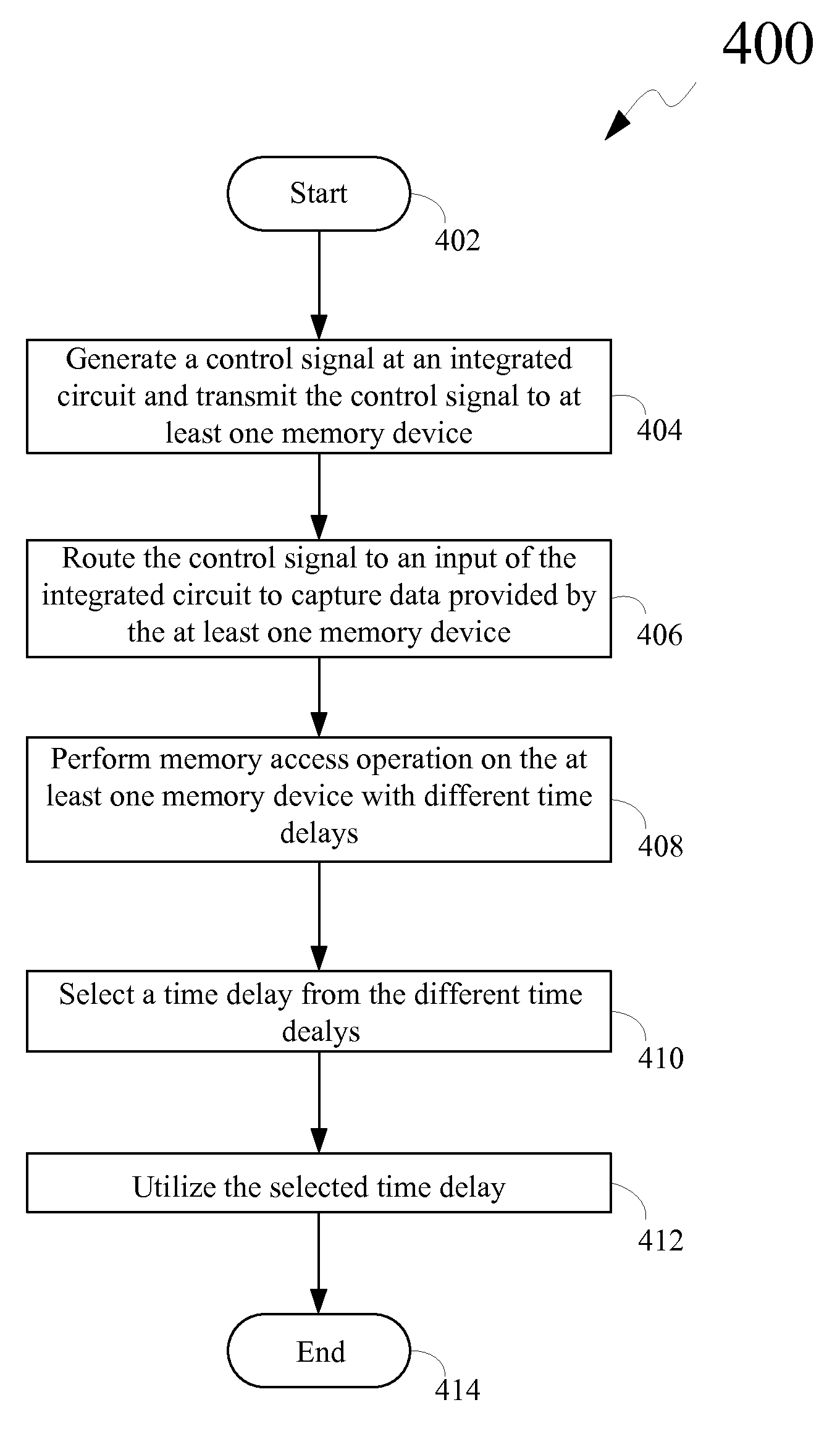
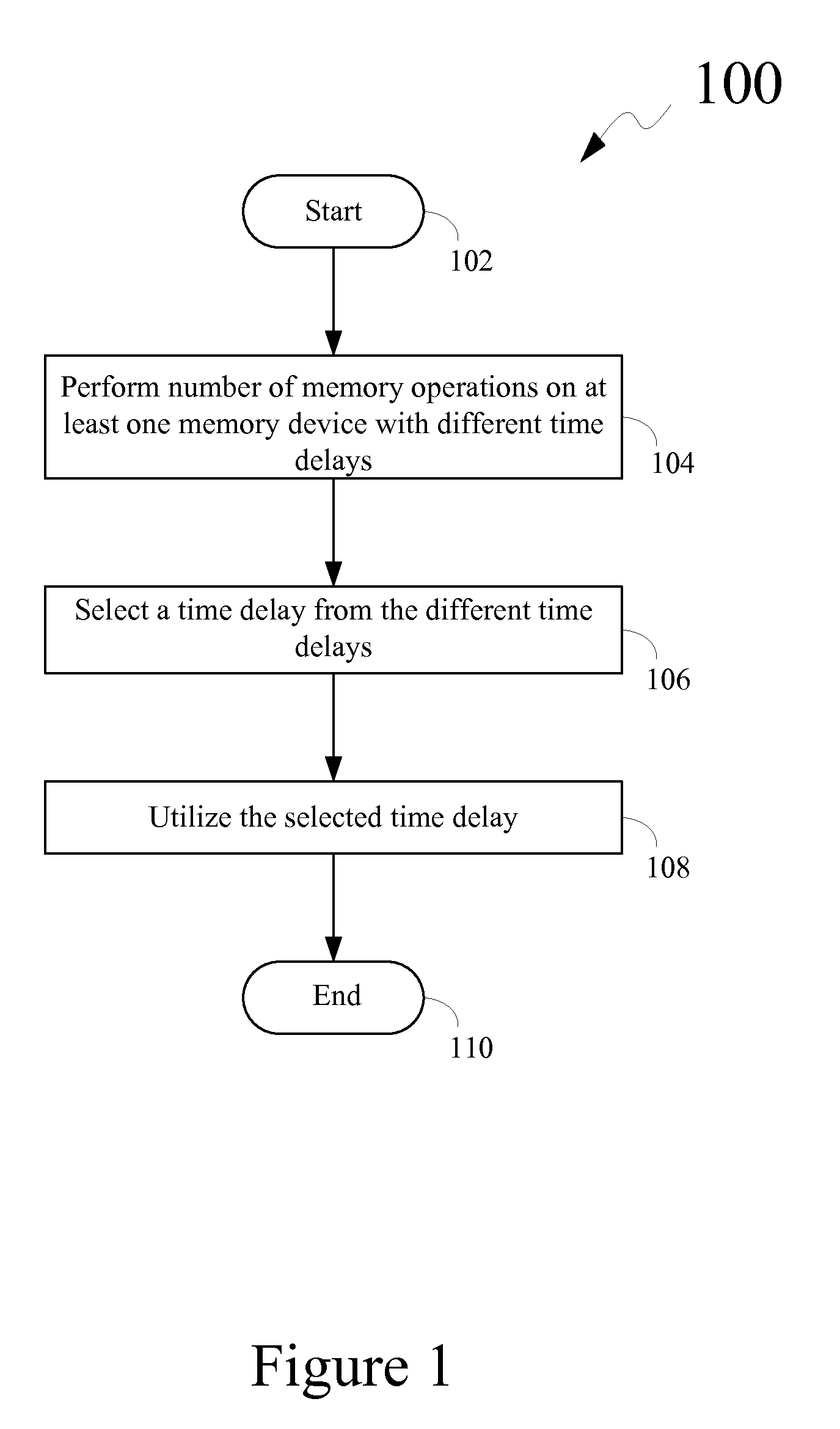
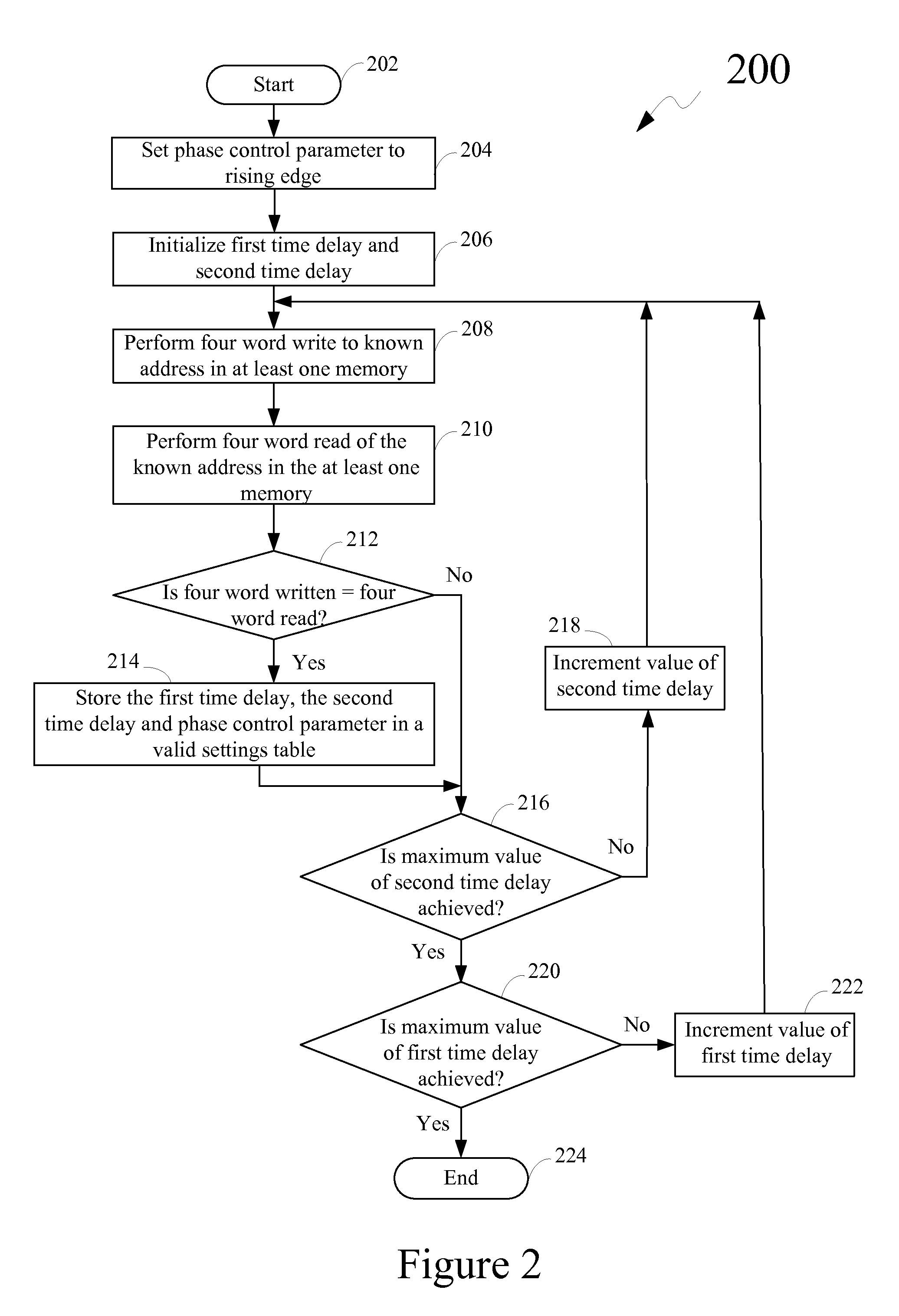
Disclosed is a method for tuning control signals associated with one or more memory devices. The method includes performing a number of memory access operations on at least one memory device and recording results of the memory access operations. Specifically, the memory access operations are performed with different time delays for a first edge of a control signal. The control signal used for capturing data is provided by the at least one memory device. The method further includes selecting a time delay from the time delays used in the memory access operations. Moreover, the method includes utilizing the selected time delay in performing subsequent memory access operations on the at least one memory device. Also disclosed is a system including at least one memory device and an integrated circuit operatively coupled to the at least one memory device. The system incorporates the method for tuning control signals.

Description

CROSS REFERENCES TO RELATED APPLICATIONS[0001]None.STATEMENT REGARDING FEDERALLY SPONSORED RESEARCH OR DEVELOPMENT[0002]None.REFERENCE TO SEQUENTIAL LISTING, ETC.[0003]None.BACKGROUND[0004]1. Field of the Disclosure[0005]The disclosure relates generally to memory devices, and, more particularly, to a method for tuning control signals in the memory devices.[0006]2. Description of the Related Art[0007]Generally, processing devices, such as computers, image processing devices, and the like utilize different type of memory devices for storing information, data, firmware and the like, therein. Conventional processing devices may utilize different types of memory devices, such as a Synchronous Dynamic Random Access Memory (SDRAM), a flash memory, a Read Only Memory (ROM), and the like depending upon specific operations such memory devices are intended to perform. An SDRAM is a volatile memory device that is based on a synchronous timing platform. Specifically, the SDRAM is adapted to resp...

Claims


Application Information

Patent Timeline
Patent Type & Authority Applications(United States)
IPC IPC(8): G11C7/00
CPCG11C7/1078G11C2207/2254G11C7/1093G11C7/109
Inventor FOLEY, NATHAN WAYNESHARPE, JAMES PATRICKWARD, JAMES ALANWAHNSIEDLER, KEITH ALLEN
Owner LEXMARK INT INC
Why Eureka
Try Eureka