Adaptive calculation of pulse compression filter coefficients for a radar signal

a radar signal and filter coefficient technology, applied in the field of pulse compression filter coefficient adaptation calculation of pulse compression filter coefficient for received signals, can solve the problems of not being able to automatically implement the process, not being able to react to signal changes (and therefore signal deficiencies), and significantly noticeable differences in the pc image, so as to achieve high side-lobe separation

Active Publication Date: 2012-06-05
HENSOLDT SENSORS GMBH
View PDF12 Cites 13 Cited by
  • Summary
  • Abstract
  • Description
  • Claims
  • Application Information

AI Technical Summary

Benefits of technology

[0017]According to the invention, an adaptive optimum PC filter hopt(t) which can be calculated online is sought for a received signal sv(t), (which, as ever, is “corrupted”; that is, it includes signal distortions and which may vary during radar operation), such that the PC results in a high-quality PC output signal in the form of a high side-lobe separation. Also, it should be possible to calculate hopt(t) online (that is, quickly and without any monitoring mechanism).

Problems solved by technology

With this method, however, it is not possible to react to signal changes (and therefore to signal deficiencies) which occur during radar operation, or to compensate for them for a high-quality pulse-compression image.
In fact, the transmitter behavior is also dependent on the frequency agility of the radar; that is, the transmitter has a different behavior at higher frequencies than at lower frequencies, resulting in significantly noticeable differences in the PC image.
In consequence it is virtually impossible to implement this process automatically without having to monitor it adequately.
This conventional iteration technique is thus unsuitable for adaptive online calculation of the PC filter coefficients.

Method used


Image

  • Adaptive calculation of pulse compression filter coefficients for a radar signal
  • Adaptive calculation of pulse compression filter coefficients for a radar signal
  • Adaptive calculation of pulse compression filter coefficients for a radar signal

Examples


Embodiment Construction

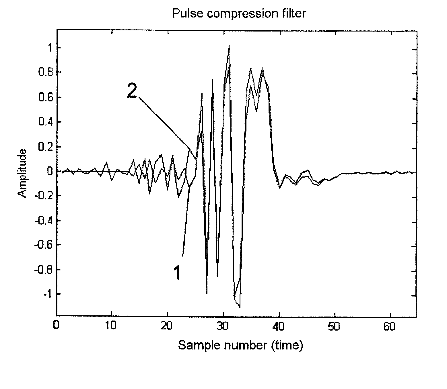
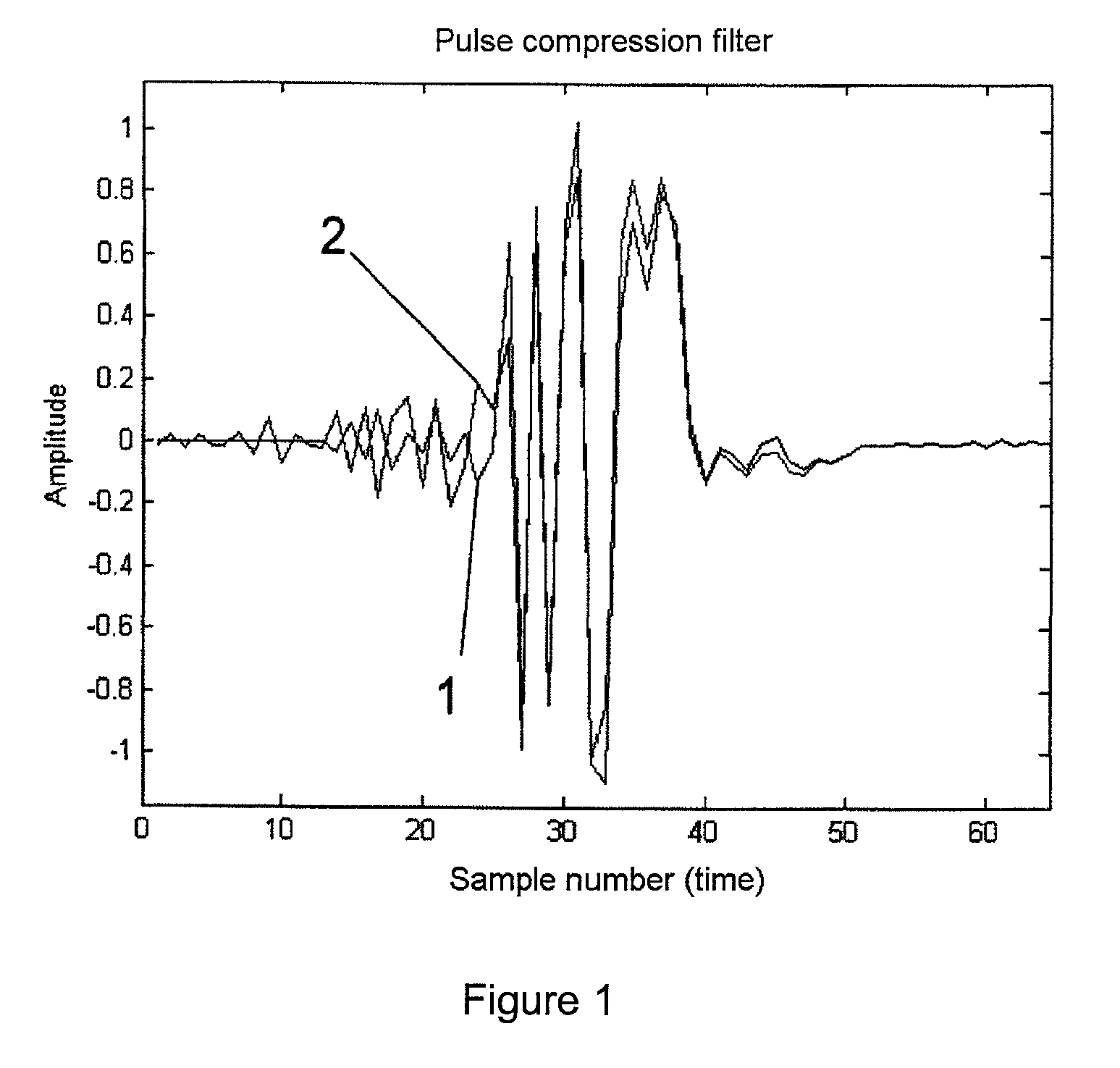
[0026]The process according to the invention will now be described based, for example, on a pulse compression code which is very well known in the specialist world: the binary code of a length 13 Barker code. This is a real-value signal with coding +++++−−++−+−+ (+ representing +1 and − representing −1). This signal and this coding represent the “uncorrupted” signal s(t) in the above formulae.

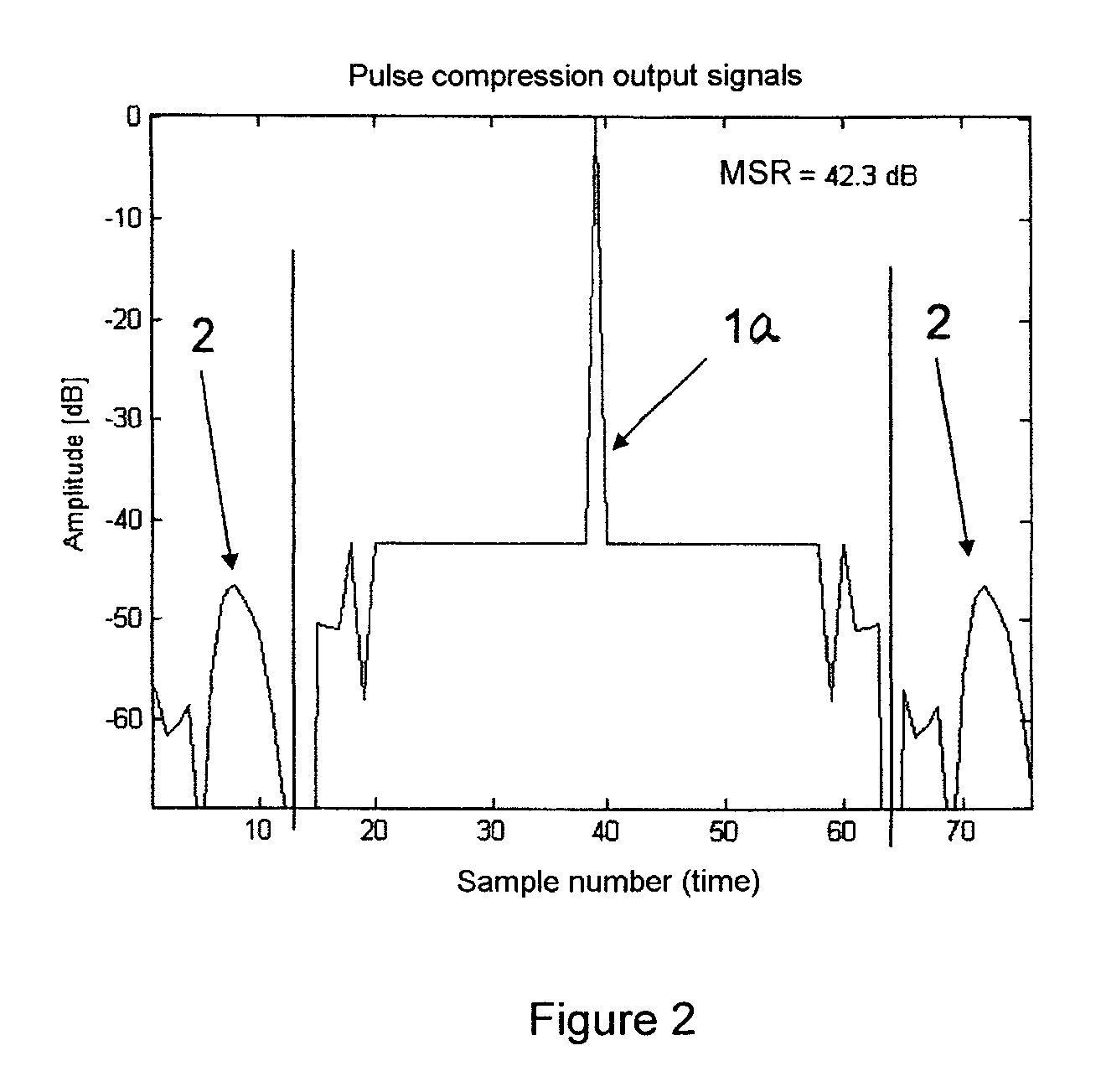
[0027]A PC-mismatched filter (MMF) of length 37 was established for s(t) using the conventional iteration method. This PC filter, which is designated by reference numeral 1 in FIG. 1, represents h(t) in the above expressions. This PC filter h(t), with pulse compression using s(t), produces the PC output signal g(t), whose magnitude is represented by reference numeral 1a in FIG. 2, and which has a high main-lobe-to-side-lobe ratio (MSR) of 42.3 dB. In addition, this PC output signal exhibits a highly homogeneous side-lobe behavior, which is highly advantageous for subsequent CFAR-circuits.

[0028]...


PUM


Abstract

In a method for adaptive calculation of pulse compression filter coefficients for a received signal in a radar installation, which received signal is evaluated with the aid of a complex pulse compression mismatch filter, a pulse compression filter coefficient set h(t) is calculated for an ideal theoretical received signal s(t) for a pulse compression mismatch filter, such that a pulse compression output signal results with a desired main lobe to side lobe ratio. A transformed set of pulse compression filter coefficients Hopt(f) for the complex pulse compression mismatch filter Hopt(f) is calculated for a distorted received signal using the following rule:Hopt⁡(f)=S⁡(f)·H⁡(f)·Sv*⁡(f)Sv⁡(f)2whereS(f): the Fourier-transform of an undistorted received signal s(t),Sv(f): the Fourier-transform of a distorted received signal sv(t),sv*(f): the complex conjugate of Sv(f),H(f): the Fourier-transform of the pulse compression mismatch filter h(t).

Description

BACKGROUND AND SUMMARY OF THE INVENTION[0001]This application is a national stage of PCT International Application No. PCT / DE2008 / 001433, filed Sep. 1, 2008, which claims priority under 35 U.S.C. §119 to German Patent Application No. 10 2007 041 669.7, filed Sep. 1, 2007, the entire disclosure of which is herein expressly incorporated by reference.[0002]The invention relates to a method and apparatus for adaptive calculation of pulse compression filter coefficients for a received signal in a radar installation, which received signal is evaluated with the aid of a complex pulse compression mismatch filter wherein a pulse compression filter coefficient set h(t) is calculated for an ideal theoretical received signal s(t) for a pulse compression mismatch filter, such that a pulse compression output signal has a desired main-lobe-to-side-lobe ratio.[0003]German patent document DE 42 30 558 A1 discloses a process for iterative calculation of pulse compression (PC) filter coefficients whic...

Claims


Application Information

Patent Timeline
Patent Type & Authority Patents(United States)
IPC IPC(8): G01S13/00G01S7/40
CPCG01S13/288G01S2007/2883G01S7/2883
Inventor HOFELE, FRANZ-XAVER
Owner HENSOLDT SENSORS GMBH
Why Eureka
Try Eureka