Systems and methods for suppressing ambiguous peaks from stepped frequency techniques

a stepped frequency and ambiguous peaks technology, applied in the field of systems and methods for suppressing ambiguous peaks, can solve the problems of cluttered display, increased ambiguous peaks, and increased sensitivity of pulse compression methods, so as to achieve clean and more accurate radar display

Inactive Publication Date: 2012-06-05
HONEYWELL INT INC
View PDF43 Cites 4 Cited by
  • Summary
  • Abstract
  • Description
  • Claims
  • Application Information

AI Technical Summary

Benefits of technology

[0004]Systems and methods of compensating for artifacts introduced in an estimated range profile determined using stepped-frequency methods are disclosed. An exemplary embodiment utilizes knowledge of the radar system design to identify locations, predict power levels, and suppress the contributions of stepped-frequency range sidelobes (ambiguous peaks) in the estimated range profile, resulting in a cleaner and more accurate radar display. The systems and methods of compensating for artifacts suppresses ambiguous peaks resulting from any stepped frequency waveform, including pulse compressed stepped frequency waveforms.

Problems solved by technology

Unfortunately, with the improvements in detection sensitivity and range resolution, any pulse compression method adds undesirable artifacts to the estimated range profile.
When pulse compressed stepped frequency pulse-trains are used, the pulse compression and stepped frequency range sidelobe artifacts combine which results in the generation of many ambiguous peaks over up-range and down-range for distances equal to the uncompressed pulse length.
Thus, the radar display is cluttered and it becomes more difficult to discriminate true object returns from signal processing artifacts, particularly as the complexity of the range profile increases.

Method used


Image

  • Systems and methods for suppressing ambiguous peaks from stepped frequency techniques
  • Systems and methods for suppressing ambiguous peaks from stepped frequency techniques
  • Systems and methods for suppressing ambiguous peaks from stepped frequency techniques

Examples


Embodiment Construction

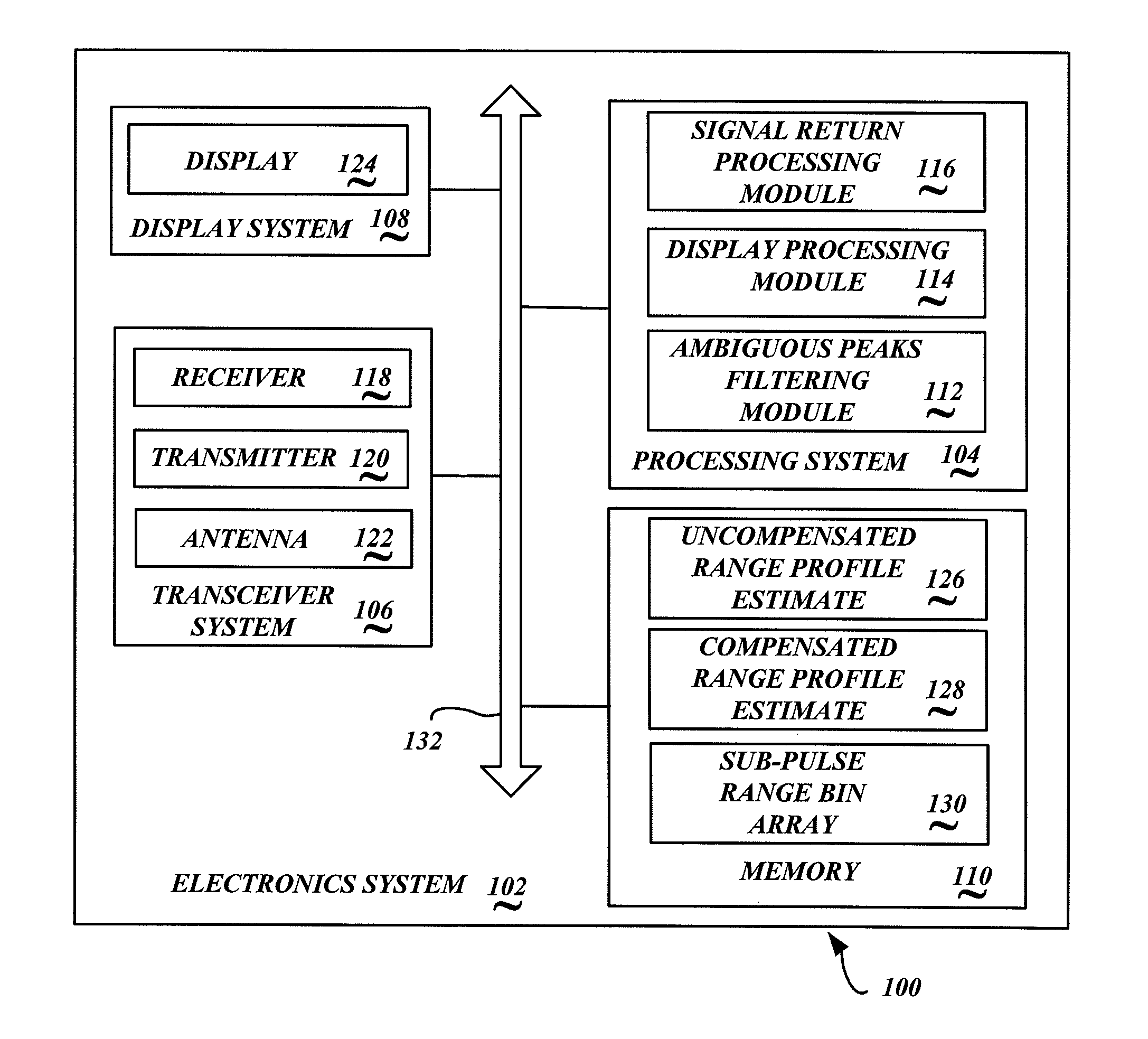
[0013]FIG. 1 is a block diagram of an exemplary embodiment of a stepped frequency ambiguous peaks compensation system 100 implemented in an electronics system 102 of an installation (not shown). The electronics system 102 includes a processing system 104, a RF transceiver system 106, a display system 108, and a memory 110. The transceiver system 106 includes a receiver 118 operable to measure radar returns, transmitter 120 that is operable to emit radar signals, and an antenna 122. The display system 108 includes a display 124. It is appreciated that the electronics system 102 may include many other components and / or systems that are not illustrated or described herein.

[0014]The above-described components, in an exemplary embodiment, are communicatively coupled together via communication bus 132. In alternative embodiments of the electronics system 102, the above-described components may be communicatively coupled to each other in a different manner. For example, one or more of the ...


PUM


Abstract

Signal compensation systems and methods compensate an estimated range profile from a plurality of detected signal returns from a true range profile, wherein the signal returns correspond to an emitted stepped frequency pulse-train. An exemplary embodiment utilizes knowledge of the radar system design to identify locations, predict power levels, and suppress the contributions of stepped-frequency range sidelobes (ambiguous peaks) in the estimated range profile, resulting in a cleaner and more accurate radar display.

Description

BACKGROUND OF THE INVENTION[0001]A pulsed radar system emits a pulsed signal, or a series of pulsed signals, in a predefined direction from its antenna. The path illuminated by the radar beam, determined by the characteristics of the antenna, is referred to as the range profile. When a pulse of radio frequency (RF) energy is emitted from the transmitter and out the antenna, objects in the range profile incident to the transmission scatter a portion of the transmitted energy back in the direction of the radar, and the receiver detects the reflected signal returns. The radar processing system then determines an estimate of the range profile consisting of a plurality of range bins. Traditionally, in a pulsed system, the time delay between the transmission and reception of the radar signal determines the range to the object and the length of the pulse emitted pulse determines range resolution. The range corresponds to the distance from the radar system, and the range resolution correspo...

Claims


Application Information

Patent Timeline
Patent Type & Authority Patents(United States)
IPC IPC(8): G01S13/18
CPCG01S13/24G01S13/282
Inventor LOGAN, GLORIAKILTY, BRENNANCHRISTIANSON, PAUL
Owner HONEYWELL INT INC
Why Eureka
Try Eureka