
Frame assembly

a frame rod and assembly technology, applied in the direction of dismountable cabinets, rod connections, couplings, etc., can solve the problems of low engagement strength between vertical frame rods and tenons, high storage and transportation costs, etc., and achieve the effect of high structural strength and easy assembly

Inactive Publication Date: 2012-06-12
LEE YUNG YU
View PDF26 Cites 17 Cited by
  • Summary
  • Abstract
  • Description
  • Claims
  • Application Information

AI Technical Summary

Benefits of technology

[0007]Therefore, the object of the invention is to provide a frame assembly that is easy to assemble and that has a relatively high structural strength.

Problems solved by technology

However, due to difficulties in assembling the corner joints and the frame rods, the conventional frame assembly is generally assembled before delivery to a consumer, thus resulting in relatively high storage and transport costs.
However, since the tenons are welded to the horizontal frame rod units, and since each of the screws hole is formed in a relatively thin segment of a respective one of the end portions of the vertical frame rods, engaging strength between the vertical frame rods and the tenons is relatively weak.

Method used


Image

  • Frame assembly
  • Frame assembly
  • Frame assembly

Examples


Embodiment Construction

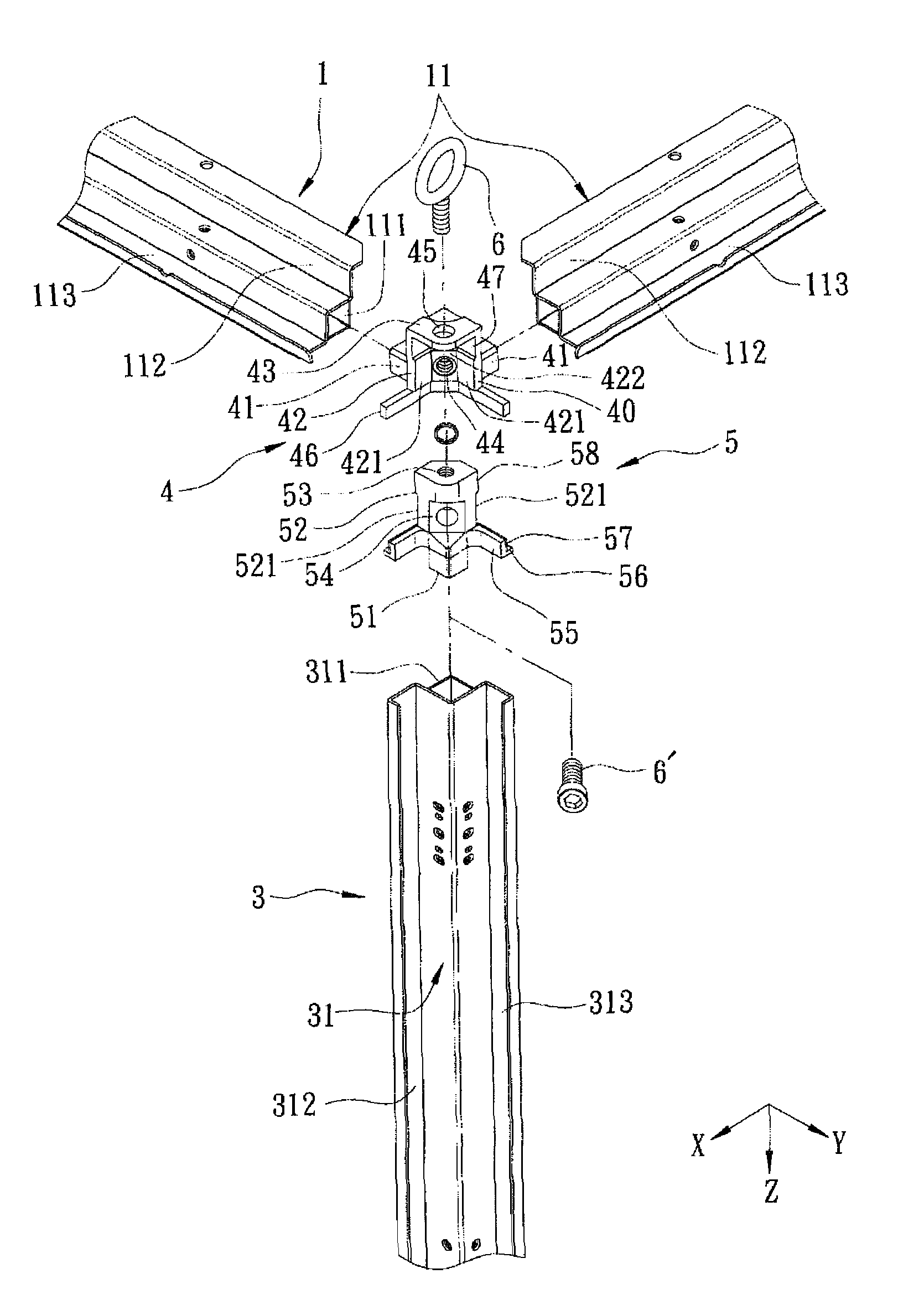
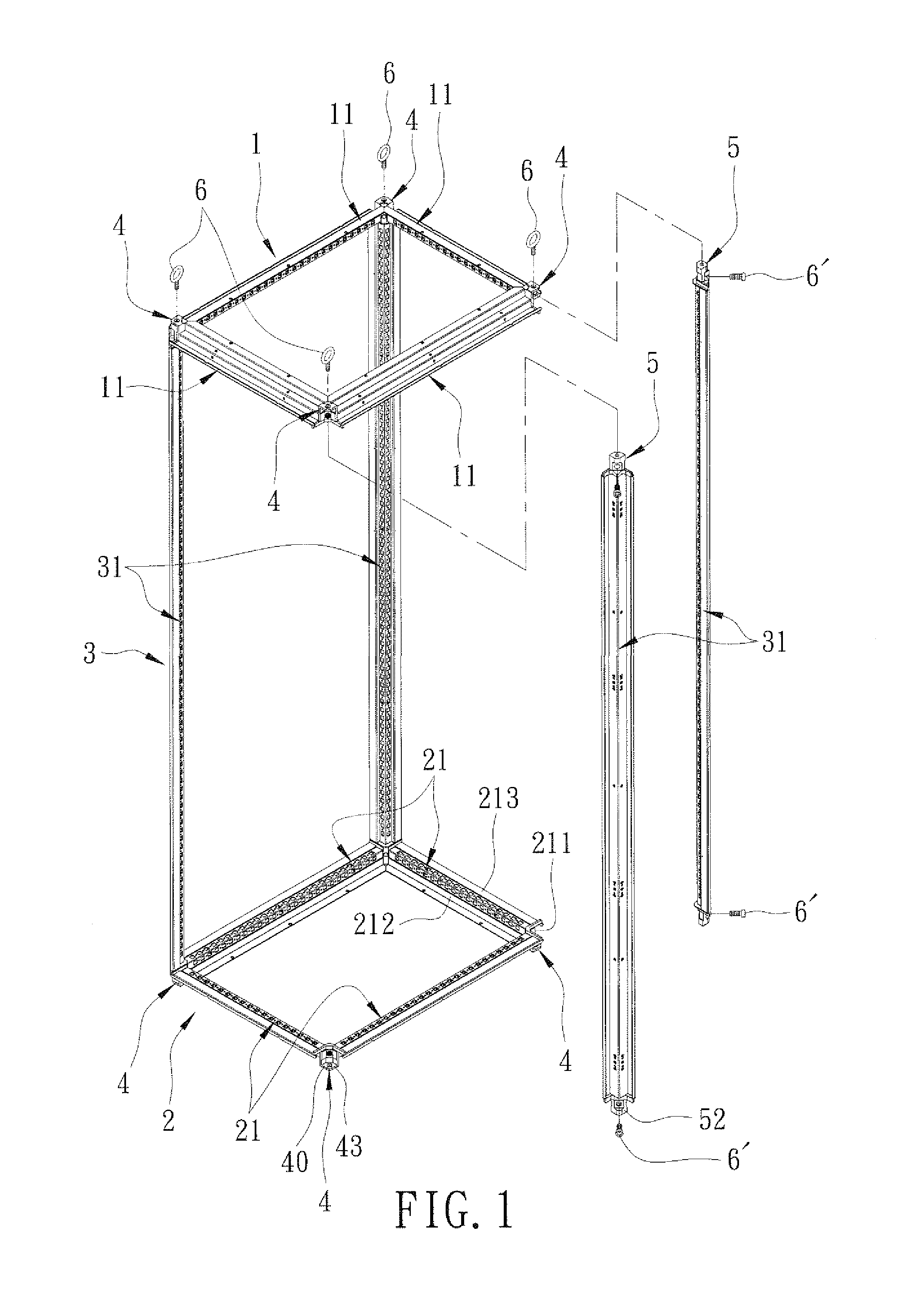
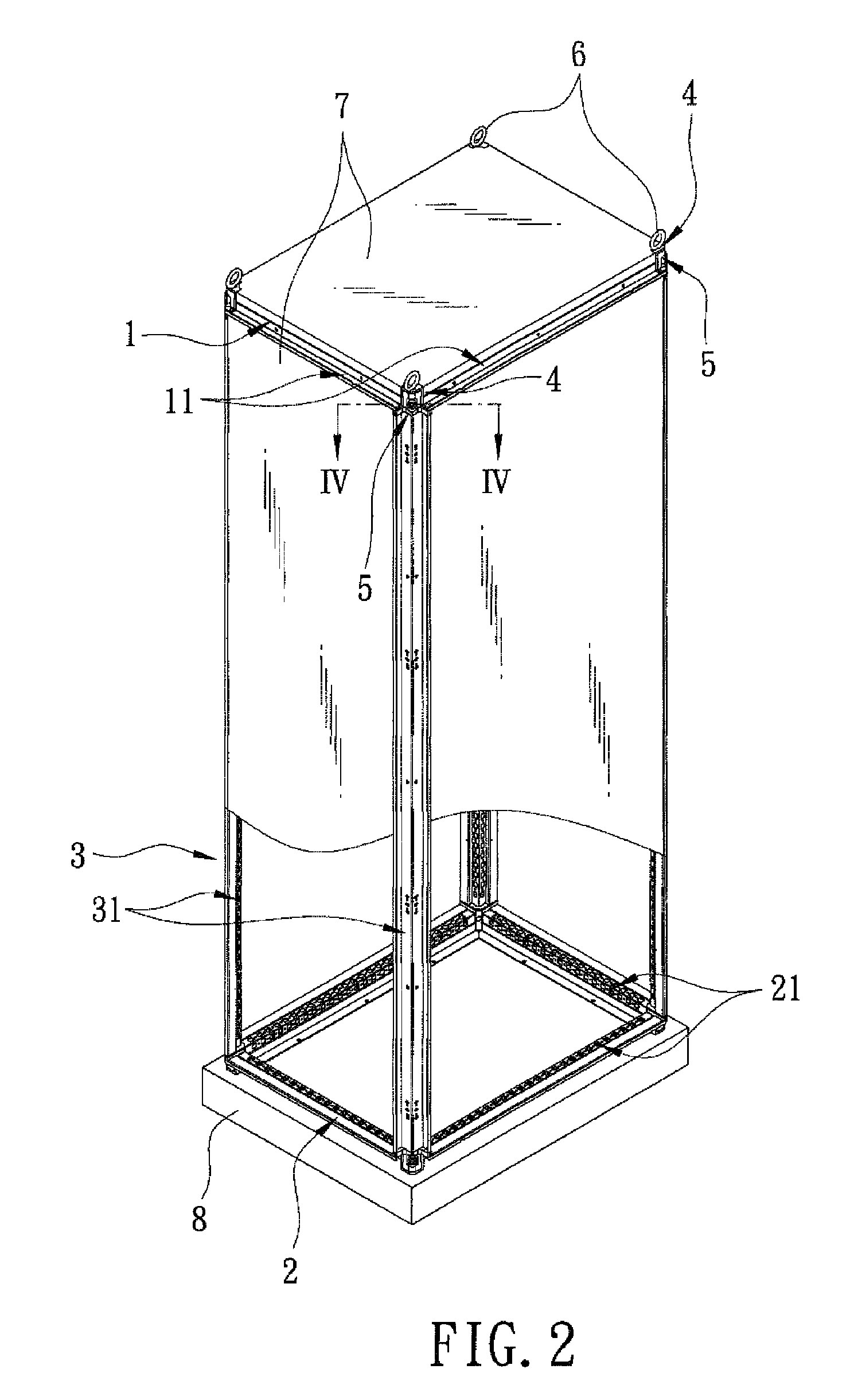
[0016]Referring to FIGS. 1 and 2, a preferred embodiment of a frame assembly according to the present invention is shown. The frame assembly includes an upper frame unit 1, a lower frame unit 2, a vertical frame unit 3, four pairs of top and bottom female connectors 4, eight male connectors 5, and a plurality of first and second bolts 6, 6′. The frame assembly is adapted to be provided on a base seat 8 and mounted with a plurality of cover plates 7 for storage of electrical equipments.

[0017]Further referring to FIG. 3, the upper frame unit 1 includes four rectangularly-arranged horizontal frame rods 11. Each of the horizontal frame rods 11 of the upper frame unit 1 includes a hollow rod body 111, a vertical wing plate 112 extending upwardly from the rod body 111, and a horizontal wing plate 113 connected to the rod body 111 and extending horizontally away from an opposite one of the horizontal frame rods 11 of the upper frame unit 1.

[0018]The lower frame unit 2 is spaced apart from ...


PUM


Abstract

A frame assembly includes upper and lower frame units, four vertical frame rods, four pairs of top and bottom female connectors, eight male connectors, and first and second bolts. Each frame unit includes four rectangularly-arranged horizontal frame rods. Each female connector interconnects an adjacent pair of the horizontal frame rods, and includes two horizontal tenons engaging respectively the adjacent pair of the horizontal frame rods. The male connectors are connected respectively to opposite ends of the vertical frame rods. Each male connector includes a vertical tenon engaging a respective one of the opposite ends of the vertical frame rods, and an engaging block mating with a respective one of the female connectors. The first and second bolts are for securing releasably and respectively the female connectors to the male connectors.

Description

CROSS-REFERENCE TO RELATED APPLICATION[0001]This application claims priority of Taiwanese application No. 099119667, filed on Jun. 17, 2010.BACKGROUND OF THE INVENTION[0002]1. Field of the Invention[0003]The invention relates to a storage device, more particularly to a frame assembly.[0004]2. Description of the Related Art[0005]Generally, a power distribution box is used to retain electrical equipments, and comprises a frame assembly and a plurality of cover plates mounted on the frame assembly. U.S. Pat. Nos. 6,062,664 and 5,806,946 disclose a kind of conventional frame assembly comprising a plurality of corner joints. Each corner joint interconnects an adjacent pair of horizontally-extended frame rods and a vertically-extended frame rod. However, due to difficulties in assembling the corner joints and the frame rods, the conventional frame assembly is generally assembled before delivery to a consumer, thus resulting in relatively high storage and transport costs.[0006]U.S. Pat. No...

Claims


Application Information

Patent Timeline
Patent Type & Authority Patents(United States)
IPC IPC(8): A47F7/00F16B7/04A47G29/00F16D1/00F16B9/00
CPCA47B47/03F16B12/30F16B12/52Y10T403/364H02B1/014Y10T403/4602Y10T403/341F16B2012/446
Inventor LEE, YUNG-YU
Owner LEE YUNG YU
Learn More