
Dental composite delivery system

a dental composite and delivery system technology, applied in the field of dental composite delivery system, can solve problems such as interfering with the complete curing of the composite applied, and achieve the effect of preventing the interfering with the curing process

Inactive Publication Date: 2012-06-12
HARRISON III LOUIE V
View PDF34 Cites 48 Cited by
  • Summary
  • Abstract
  • Description
  • Claims
  • Application Information

AI Technical Summary

Benefits of technology

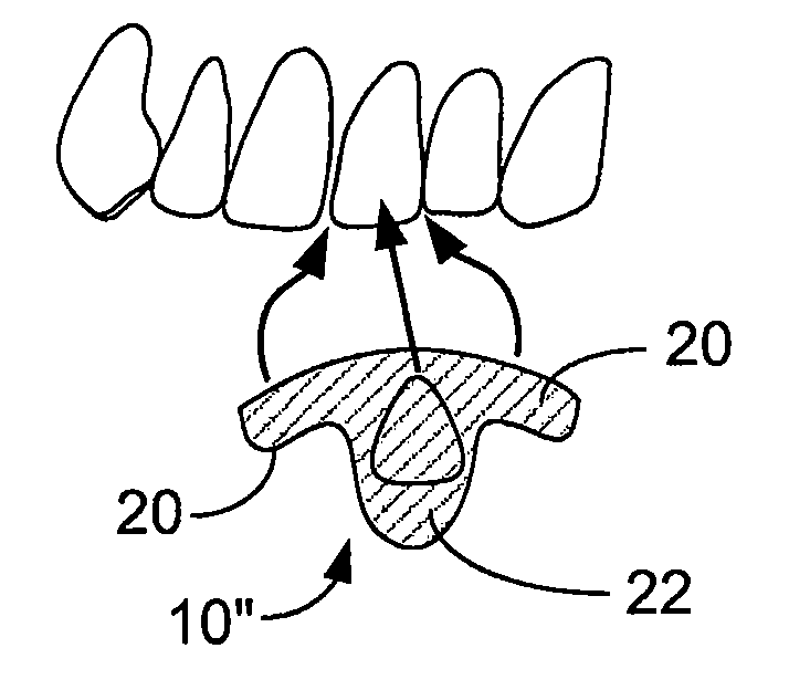
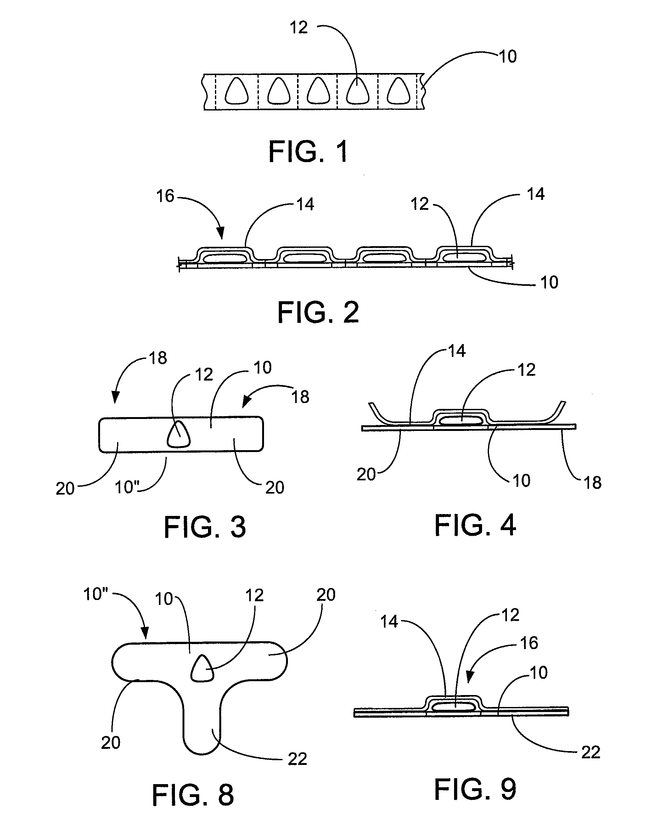
[0022]In use, the protective cover film is removed from the unit of composite and the single unit is carefully placed over the region of the tooth to be resurfaced, and then the composite is contoured, preferably while the carrier film is still in place by spatuling over the film rather than directly on the composite. In so doing, the surface of the unit composite being worked is not exposed to the air such that an oxygen inhibited layer builds up on the composite which otherwise interferes with the complete curing of the composite applied. Additionally, as those familiar with the procedure, the composite material readily sticks to anything that touches it, including dentists tools such as the spatula. By the inclusion of the film, spatuling may be smoothly accomplished by working the composite under the film without direct contact of the spatula, allowing a much more expedient application with less accumulation of composite on the spatula.

Problems solved by technology

In so doing, the surface of the unit composite being worked is not exposed to the air such that an oxygen inhibited layer builds up on the composite which otherwise interferes with the complete curing of the composite applied.

Method used


Image

  • Dental composite delivery system
  • Dental composite delivery system
  • Dental composite delivery system

Examples


Embodiment Construction

[0038]The present invention relates to the field of cosmetic dentistry wherein the visible teeth, such as the incisors and cuspids, if they become diseased, disfigured or discolored, are treated with an aesthetic restoration to improve, if not duplicate the original appearance. This invention is best understood by comparison with the current methods for applying these aesthetic composite restorations.

[0039]As related in the Background of the Invention, currently used composites are either mixed immediately prior to application to the tooth followed by being troweled or spatulated on the tooth, to as closely to the final profile as is possible. In working with the mixed composite, working time is limited since the polymerization of the resin begins with the mixing of the two components of the composite. In the instance of the use of a light cured resin, the composite is usually delivered to a tooth from a syringe, and is then spatulated to the final profile. While the polymerization ...


PUM


Abstract

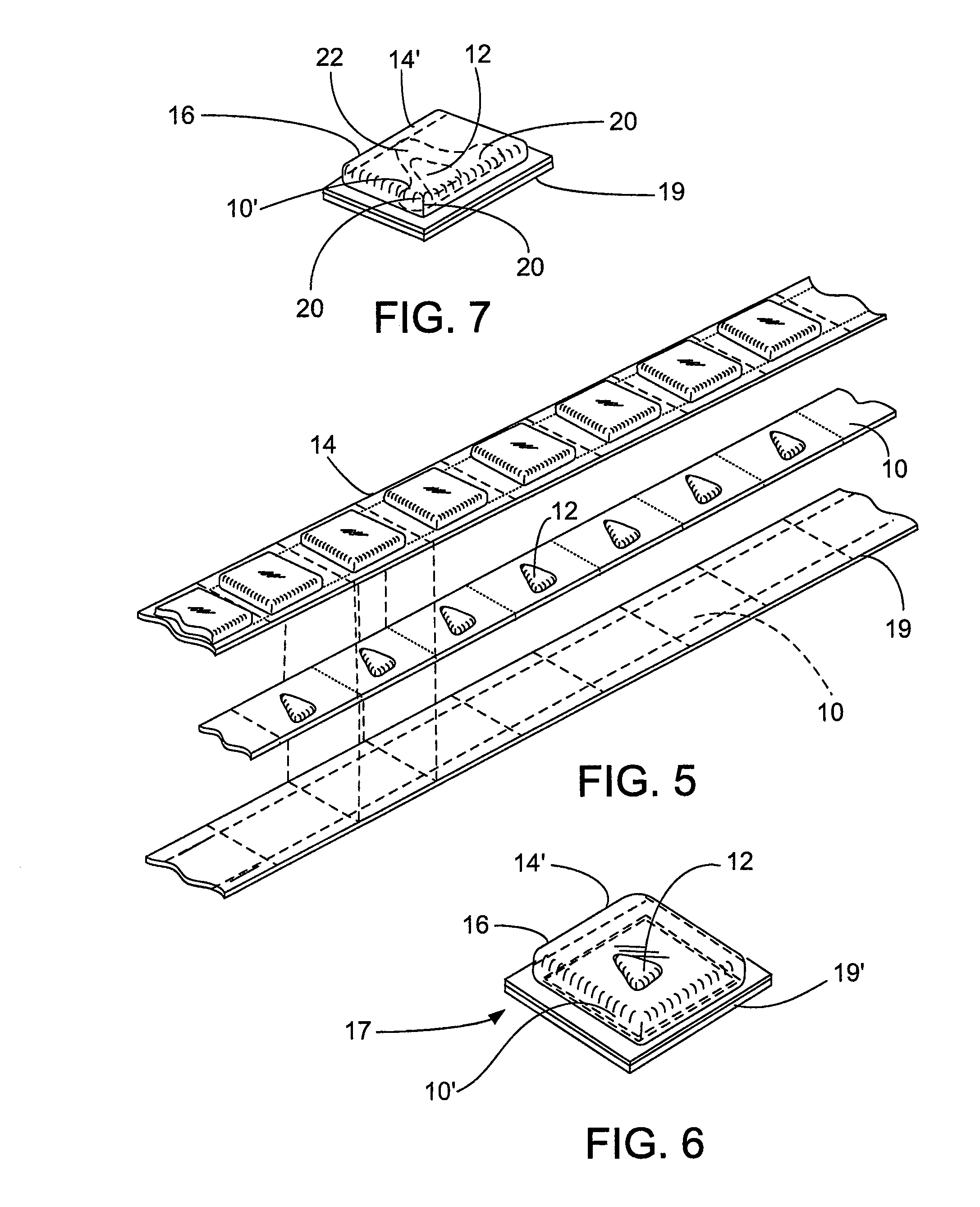
A packaged unit of composite for performing an aesthetic restoration. The unit is mounted on a polymeric film carrier material and is covered and sealed with the same or otherwise suitable covering film. The carrier film may be an elongated strip containing serially placed units of composite, each readily separable from the strip for individual usage. This packaging is in light restrictive outer packaging since the preferred unit of composite is of a light-cured material such as bis-GMA. In preferred packaging, the unit dose is singular and applicable to the tooth surface with the film carrier which is adapted with tabs to facilitate handling and the draping or damming of the subject tooth from adjacent teeth to facilitate application of the composite. The composite is then worked, i.e., formed on the tooth with the film intermediate the composite and the customary forming tools. In preferred embodiments, the single unit packaging of composite is mounted on a clear carrier film which includes embrasure tabs for selective insertion in the embrasure between the teeth, and in a further preferred embodiment, the carrier film includes an incisal tab to cover the incisal edge of the tooth. The clear carrier is contained in further outer packaging which limits actinic radiation from reaching the composite.

Description

CROSS REFERENCE TO RELATED APPLICATIONS[0001]This application is a Continuation Application (Division) of U.S. patent application Ser. No. 10 / 766,632, filed Jan. 28, 2004, which claims priority of Provisional Patent Application No. 60 / 442,989, filed Jan. 28, 2003, the contents of all of which are fully incorporated by reference.STATEMENT REGARDING FEDERALLY SPONSORED RESEARCH OR DEVELOPMENT[0002]Not Applicable.REFERENCE TO A “MICROFICHE APPENDIX”[0003]Not ApplicableBACKGROUND OF THE INVENTION[0004]1. Field of the Invention[0005]This invention relates to a method and system for the placement and installation of a synthetic resin composite as an aesthetic restoration of the surface on a tooth, which is otherwise discolored or disfigured.[0006]2. General Background of the Invention[0007]The placement of composites or plastic surfacing or fillings, are widely used as aesthetic restorations. The restorations mimic the natural tooth color and shape to present a “filling” which replaces or...

Claims


Application Information

Patent Timeline
Patent Type & Authority Patents(United States)
IPC IPC(8): A61C5/04
CPCA61C5/04A61C5/125A61C5/062A61C5/62A61C5/85
Inventor HARRISON, III, LOUIE V.
Owner HARRISON III LOUIE V
Learn More