

Optical film, liquid crystal panel, and liquid crystal display apparatus
a liquid crystal display and optical film technology, applied in non-linear optics, instruments, optics, etc., can solve the problem that the conventional liquid crystal display apparatus hardly develops a colorless neutral display in all azimuth angle directions, and achieve the effect of reducing the thickness of the liquid crystal display apparatus
- Summary
- Abstract
- Description
- Claims
- Application Information
AI Technical Summary
Benefits of technology
Problems solved by technology
Method used
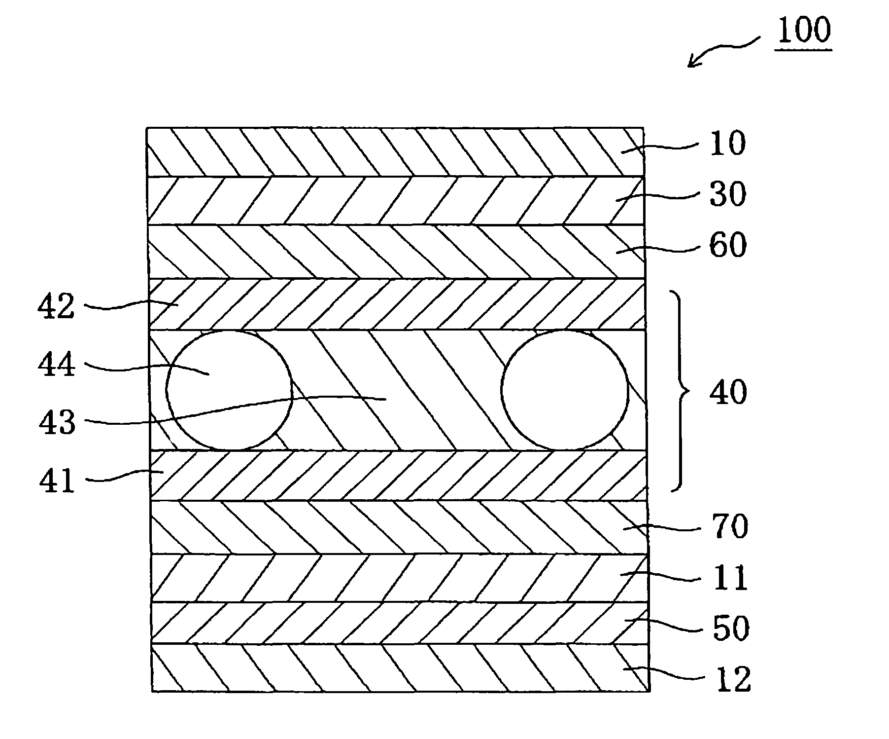
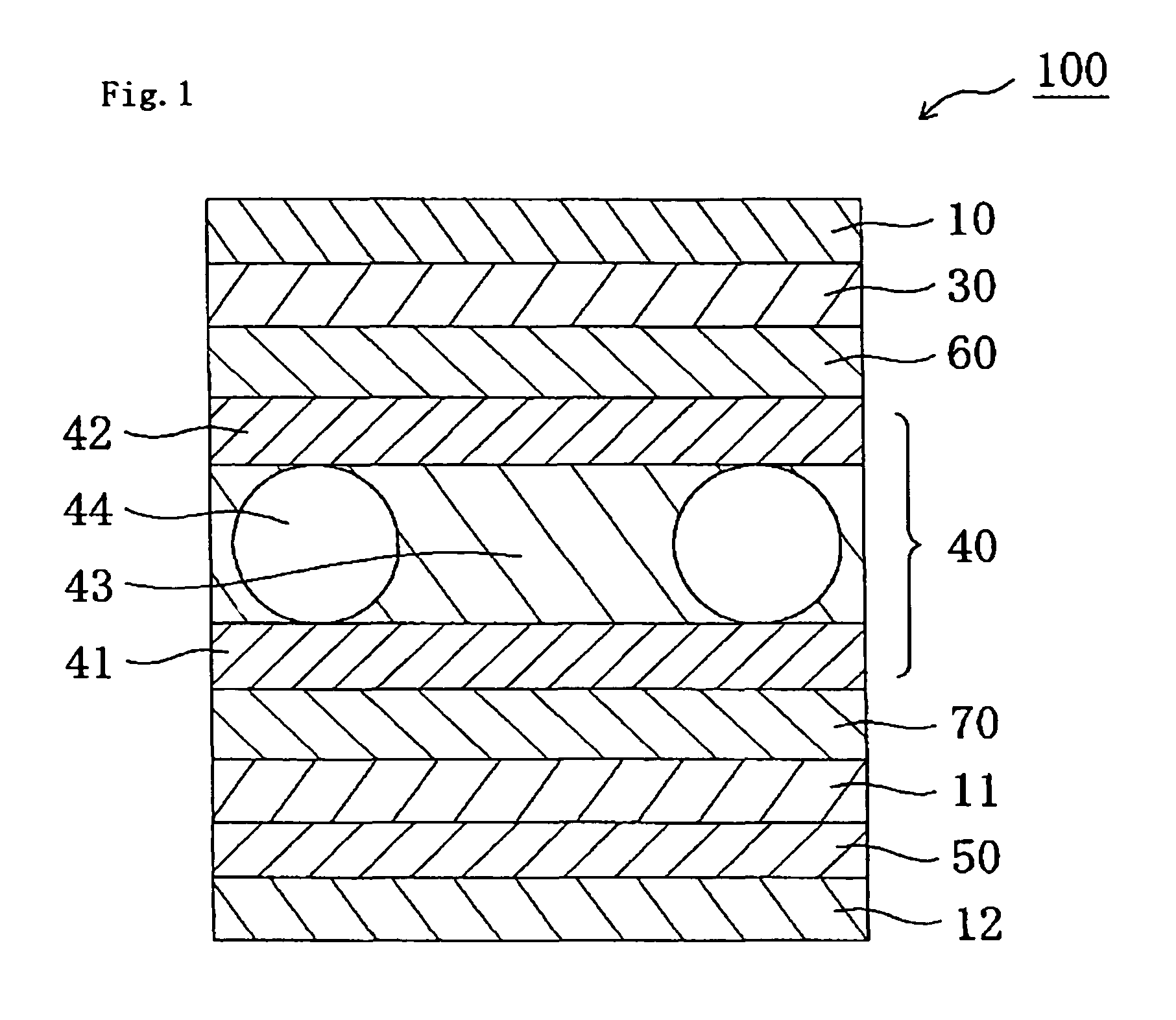
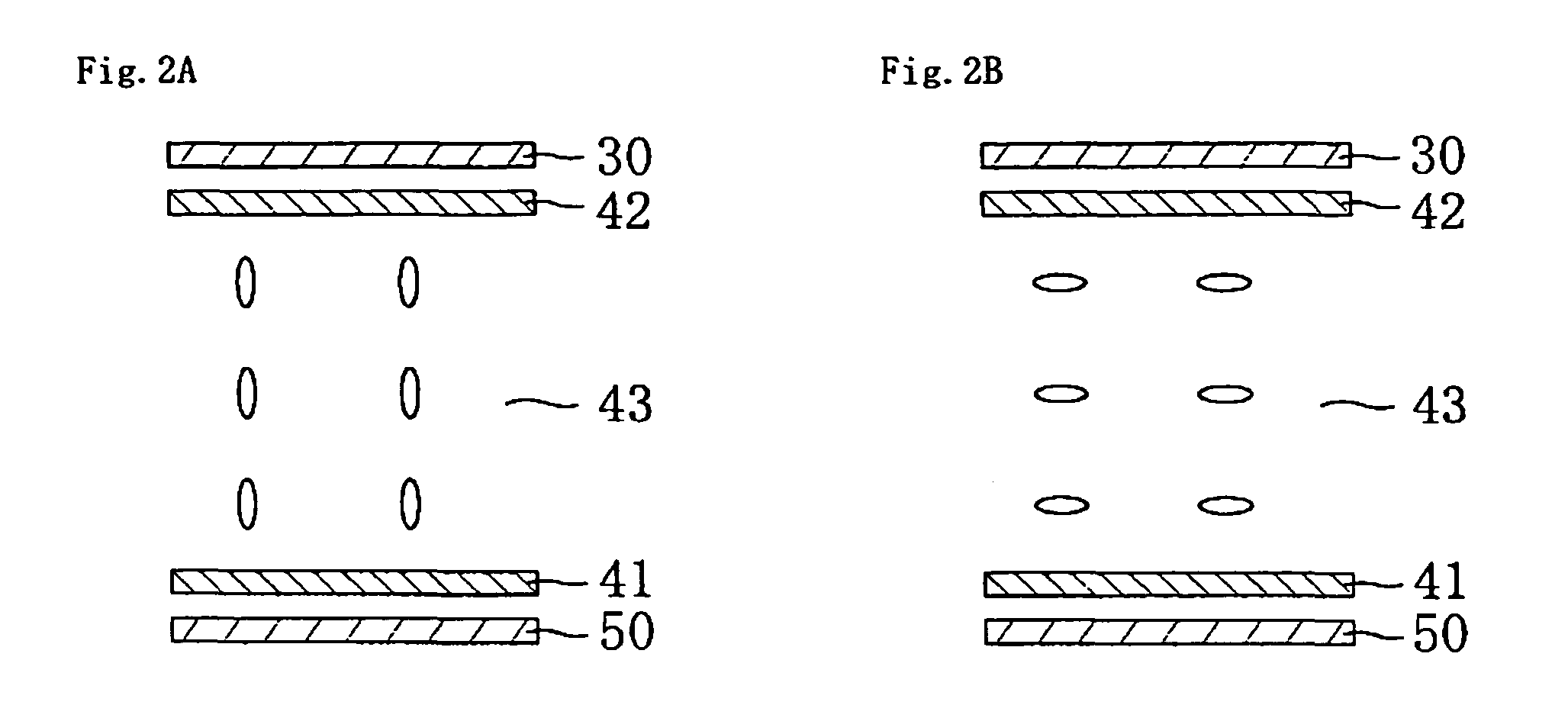
Image

Examples
reference example 1
Production of Polarizer
[0253]A polyvinyl alcohol film was colored in an aqueous solution containing iodine, and the resultant was uniaxially stretched to a six times length between rolls with different speed ratios in an aqueous solution containing boric acid, to thereby produce a polarizer.
reference example 2
Preparation of Polyvinyl Alcohol-Based Adhesive
[0254]An aqueous solution of a polyvinyl alcohol-based adhesive was prepared by adjusting to a concentration of 0.5 wt % an aqueous solution containing 20 parts by weight of methylol melamine with respect to 100 parts by weight (degree of acetylation of 13%) of a polyvinyl alcohol resin subjected to acetoacetyl modification.
example 1
Production of First Birefringent Layer
[0255]A continuous norbornene-based resin film (“ZEONOR”, tradename, available from Zeon Corporation, thickness of 100 μm, photoelastic coefficient of 3.10×10⁻¹² m2 / N) was uniaxially stretched to a 1.46 times length at 150° C., to thereby produce a continuous first birefringent layer. The first birefringent layer had a thickness of 80 μm, an in-plane retardation Δnd of 140 nm, and a thickness direction retardation Rth of 140 nm.
Production of Laminate of TAC / Polarizer / First Birefringent Layer
[0256]Triacetyl cellulose (TAC) (thickness of 80 μm) and the polarizer were laminated by using an adhesive.
[0257]A surface of the thus-obtained first birefringent layer was subjected to easily adhesive treatment (silicon primer, “APZ6661”, trade name, available from Dow Corning Toray Co., Ltd., thickness of easily adhesive layer=50 nm), and the first birefringent layer was laminated on a polarizer side of the laminate of TAC and the polarizer by using an adhe...
PUM
| Property | Measurement | Unit |
|---|---|---|
| thickness | aaaaa | aaaaa |
| thickness direction retardation | aaaaa | aaaaa |
| azimuth angle | aaaaa | aaaaa |
Abstract
Description
Claims
Application Information