
Printing device with conveyor belt

a conveyor belt and printing device technology, applied in printing, typewriters, other printing apparatuses, etc., can solve the problems of not being environmentally friendly for operators, inefficient to fill daily all these inkjet printing devices, and consuming a lot of production time to remove sticky layers, etc., to improve the handling of specific print receivers.

Active Publication Date: 2019-09-05
AGFA NV
View PDF0 Cites 2 Cited by
  • Summary
  • Abstract
  • Description
  • Claims
  • Application Information

AI Technical Summary

Benefits of technology

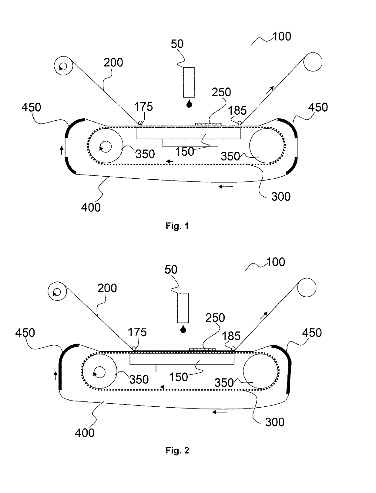
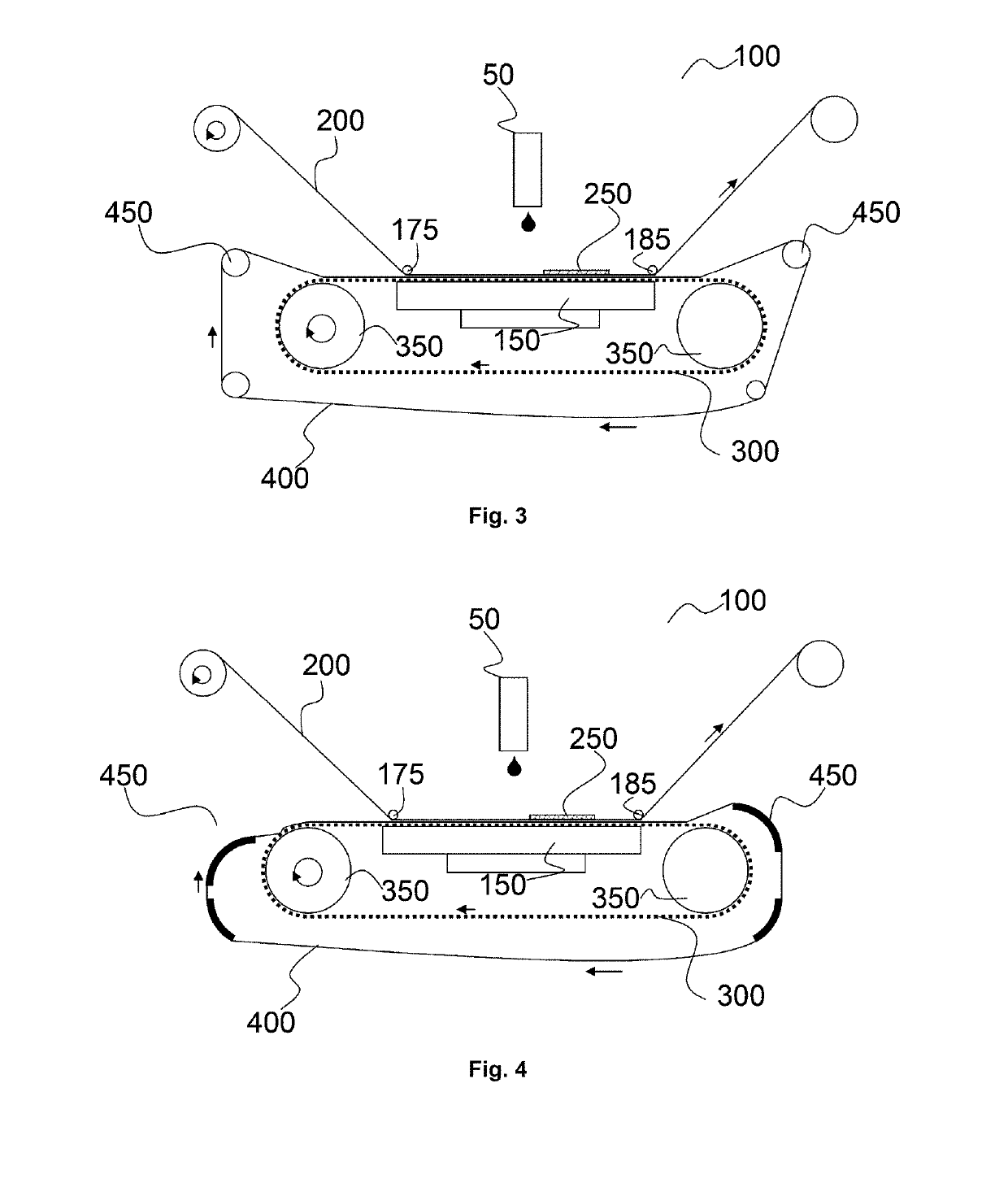
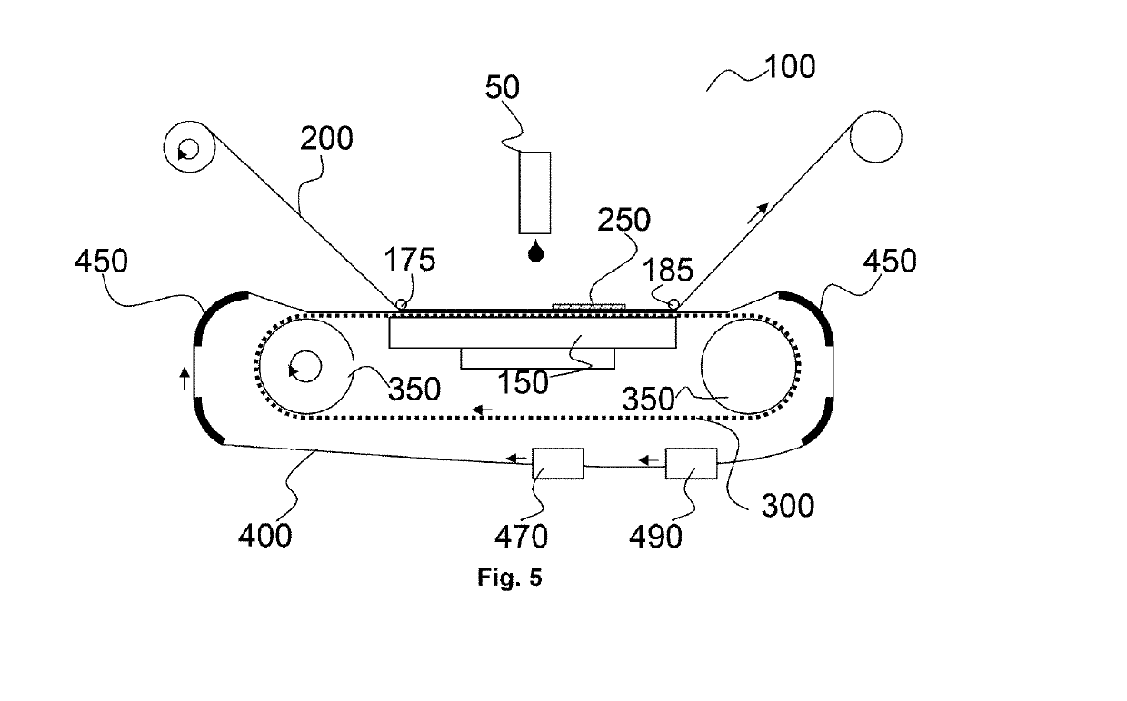
The present invention provides an inkjet printer and printing method that can handle specific print receivers, such as crease-sensitive, brittle, edge-curl, and rough back-side print receivers. The printer uses a second conveyor belt that can be tensioned independently of the first conveyor belt, which makes it easier to handle these print receivers and improves print quality. The tension of the second conveyor belt is lower than the first conveyor belt to prevent crinkling or bad adhering of the print receiver. The second conveyor belt can be easily replaced or mounted for different print receivers, which makes it economically advantageous for the printing industry. The invention also uses a film for forming the second conveyor belt, which is a low-cost and re-usable material.

Problems solved by technology

One of the issues with the current inkjet printing device from the state-of-the-art is the possibility to handle, to transport, to print on all kind of substrates.
The use of multiple inkjet printing devices makes it economically inefficient to fill daily all these inkjet printer devices with print-jobs and in an industrial environment 7-days-on-7 days.
The removal of such sticky layer takes a huge amount from the production time and is mostly not environmentally friendly for the operator of the inkjet printer and also apply a new sticky layer with another kind of adhesive takes a second huge amount from the production time.

Method used


Image

  • Printing device with conveyor belt
  • Printing device with conveyor belt
  • Printing device with conveyor belt

Examples


Embodiment Construction

Printing Device

[0035]A printing device is a device which marks a pattern on a surface of a print receiver (200) such as paper. The marking of a pattern on a surface is also called printing. The pattern represents an image which may be text, photograph, graphic or logo. The pattern is mostly the result of a halftoning method of the image such as an error-diffusion method or an amplitude modulation halftoning method. The pattern may have an achromatic or chromatic color.

[0036]The marking of the printing device may be done by any conventional printing technology such as offset printing, gravure printing, letterpress printing, screen printing. These conventional printing methods are all described in ‘Chapter 2. Printing Technologies With Permanent Printing Master’, P 204-448 in ‘Handbook of Print Media, Technologies and Production Methods’ by Helmut Kipphan, ISBN 3-540-67326-1 Springer-Verlag Berlin Heidelberg New York, 2001. Such printing device is also called a conventional printing d...


PUM


Abstract

An inkjet printer, and a printing method with the inkjet printer, includes a first conveyor belt wrapped around a vacuum table and supported by an upstream pulley and a downstream pulley and a vacuum area on the first conveyor belt, and a second conveyor belt wrapped-around the first conveyor belt and supported by an upstream sliding support and a downstream sliding support. The second conveyor belt is adhered in the vacuum area by vacuum power and a print receiver is attached to the second conveyor belt for conveying and printing.

Description

CROSS REFERENCE TO RELATED APPLICATIONS[0001]This application is a 371 National Stage Application of PCT / EP2017 / 078547, filed Nov. 8, 2017. This application claims the benefit of European Application No. 16198588.2, filed Nov. 14, 2016, which is incorporated by reference herein in its entirety.BACKGROUND OF THE INVENTION1. Field of the Invention[0002]The present invention relates to a printing device, such as an offset press, or an inkjet printer, to print on difficult manageable print receivers which are conveyed by a conveyor belt in the printing device.2. Description of the Related Art[0003]Inkjet printing devices with a vacuum belt, as vacuum support for the substrate, to transport a substrate underneath a print head are well-known. Such inkjet printing devices currently are adapted for sign & display market with small sized substrates to much larger substrates or multiple substrates, printed at the same time, for industrial market; and special substrates such as manufacturing m...

Claims


Application Information

Patent Timeline
IPC IPC(8): B41J11/00
CPCB41J11/007B41J11/0085B41J3/407B41J3/4078
Inventor DE ROECK, LUC
Owner AGFA NV
Learn More