Liquid ejecting head, piezoelectric element, and liquid ejecting apparatus

a piezoelectric element and liquid ejecting technology, applied in printing and other directions, can solve the problem of low piezoelectric layer movement inhibition of protective film, and achieve the effect of increasing the displacement amount, preventing degradation, and increasing the area

Active Publication Date: 2009-10-01
SEIKO EPSON CORP
View PDF0 Cites 3 Cited by
  • Summary
  • Abstract
  • Description
  • Claims
  • Application Information

AI Technical Summary

Benefits of technology

[0009]Since the upper electrode of the piezoelectric element is formed so as to extend over the upper surface of the piezoelectric layer and the upper portion of the side faces of the piezoelectric layer, it is possible to increase the area where electric field is produced during driving of the piezoelectric element. Moreover, since the protective film is not configured to cover an entire of the piezoelectric element but is configured to cover only the portions of the piezoelectric layer, which are not covered by the upper electrode, the possibility that the movement of the piezoelectric layer is inhibited by the protective film is low. Therefore, according to the configuration, it is possible to further increase the displacement amount in response to driving of the piezoelectric element. In this case, since the piezoelectric layer is covered by the upper electrode and the protective film, it is possible to prevent degradation thereof due to moisture.
[0010]In the above aspect of the liquid ejecting head of the invention, a width of the piezoelectric layer may increase toward the lower electrode, a thickness of a portion of the upper electrode formed above the side faces may gradually decrease toward the lower electrode, and the protective film may be provided so as to overlap with the gradually decreasing thickness portion of the upper electrode. If the side faces of the piezoelectric layer are sloped surfaces, electric field can be produced over a wide range of areas when the upper electrode is configured to cover the upper surface and the side faces of the piezoelectric layer. Therefore, it is possible to further increase the displacement amount in response to driving of the piezoelectric element. Moreover, the portion of the upper electrode formed above the side faces has a width thereof which gradually decreases toward the lower portions of the side faces, and the protective film is provided so as to overlap with the gradually decreasing thickness portion of the upper electrode. Therefore, the protective film is easily adhered onto the piezoelectric layer, and thus the degradation of the piezoelectric element can be prevented.
[0011]In the above aspect of the liquid ejecting head of the invention, the upper electrode may be configured to cover an upper half portion of each of the side faces of the piezoelectric layer. Owing to such a configuration, it is not only possible to prevent the upper electrode and the lower electrode from making contact with each other to be shorted but also to further increase the displacement amount.
[0012]According to another aspect of the invention, there is provided a piezoelectric element including: a lower electrode formed above a substrate; a piezoelectric layer formed above the lower electrode; and an upper electrode that covers an upper surface of the piezoelectric layer and an upper portion of side faces of the piezoelectric layer, in which a protective film is formed above portions of the piezoelectric layer, which are not covered by the upper electrode. In such a piezoelectric element, it is possible to further increase the displacement amount.
[0013]According to a further aspect of the invention, there is provided a liquid ejecting apparatus including the liquid ejecting head according to the above aspect of the invention. Since the liquid ejecting apparatus is equipped with the liquid ejecting head having good ink ejection characteristics, the printing characteristics of the liquid ejecting apparatus can be improved.

Problems solved by technology

Moreover, since the protective film is not configured to cover an entire of the piezoelectric element but is configured to cover only the portions of the piezoelectric layer, which are not covered by the upper electrode, the possibility that the movement of the piezoelectric layer is inhibited by the protective film is low.

Method used


Image

  • Liquid ejecting head, piezoelectric element, and liquid ejecting apparatus
  • Liquid ejecting head, piezoelectric element, and liquid ejecting apparatus
  • Liquid ejecting head, piezoelectric element, and liquid ejecting apparatus

Examples


Embodiment Construction

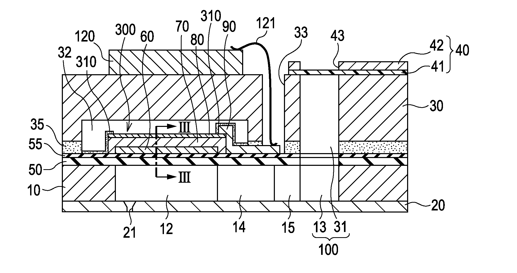
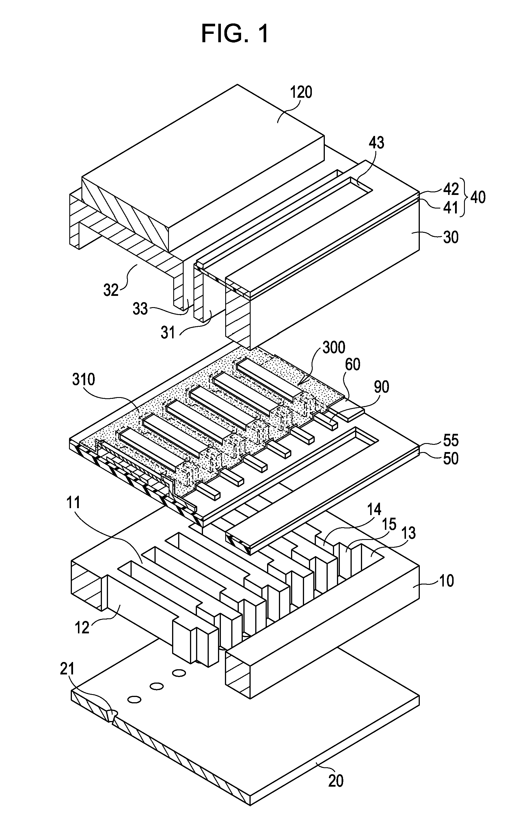
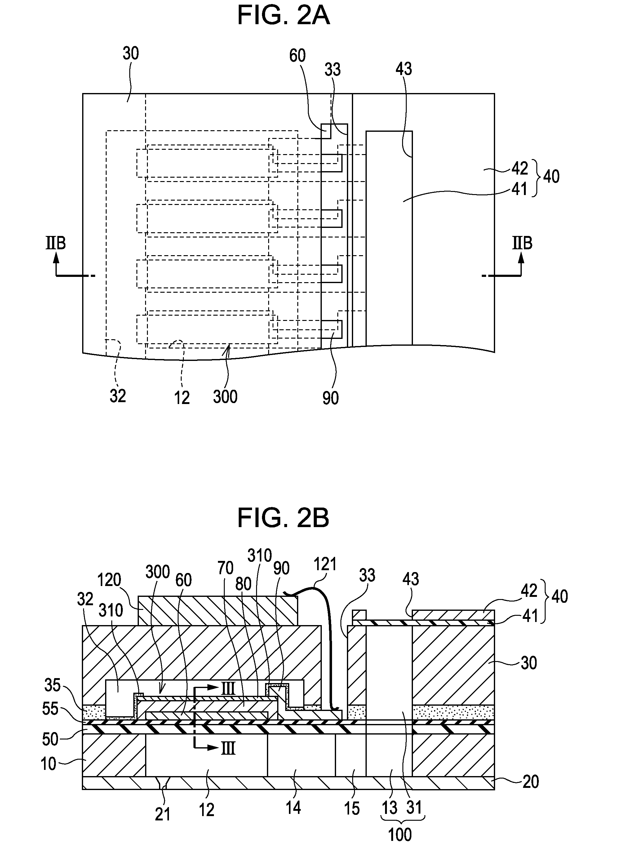
[0019]Exemplary embodiments will be described herein below with reference to the accompanying drawings. FIG. 1 is an exploded perspective view showing a simplified structure of an ink ejecting recording head which is an example of a liquid ejecting head according to the present embodiment. FIG. 2A is a top plan view of FIG. 1, and FIG. 2B is a sectional view taken along the line IIA-IIA′ in FIG. 2A. For better understanding of the drawing, a later-described protective film 310 is not depicted in FIG. 2A.

[0020]A flow path forming substrate 10 is formed of a single crystal silicon substrate which has a plane (110) of the plane orientation in the present embodiment. An elastic film 50 which is preliminarily formed of silicon dioxide by thermal oxidation is formed on one surface of the flow path forming substrate 10. An insulation film 55 formed of zirconium oxide (ZrO2) or the like is formed on the elastic film 50. On the other surface of the flow path forming substrate 10, pressure ge...


PUM


Abstract

A liquid ejecting head includes a piezoelectric element in which a lower electrode, a piezoelectric layer, and an upper electrode are laminated in this order, and a flow path forming substrate in which the piezoelectric element is formed above one surface thereof and a pressure generating chamber being communicated with a nozzle opening is provided, in which the upper electrode is formed so as to extend over an upper surface of the piezoelectric layer and an upper portion of side faces of the piezoelectric layer, and a protective film is formed above portions of the piezoelectric layer, which are not covered by the upper electrode.

Description

[0001]This application claims priority to Japanese Patent Application No. 2008-088176 filed on Mar. 28, 2008 and Japanese Patent Application No. 2009-002958, filed on Jan. 8, 2009, the entire disclosures of which are expressly incorporated by reference herein.BACKGROUND[0002]1. Technical Field[0003]The present invention relates to a liquid ejecting head, a piezoelectric element, and a liquid ejecting apparatus.[0004]2. Related Art[0005]As an example of a liquid ejecting head, an ink ejecting recording head in which a piezoelectric element consisting of an upper electrode, a piezoelectric layer, and a lower electrode is used as a pressure generating unit is known (reference should be made to, for example, claim 2 and FIG. 6 of JP-A-2000-246888). In such an ink ejecting recording head, an insulation layer for preventing moisture degradation of the piezoelectric layer is formed in a state of covering the piezoelectric layer and the upper electrode.[0006]According to the above-mentioned...

Claims


Application Information

Patent Timeline
Patent Type & Authority Applications(United States)
IPC IPC(8): B41J2/045
CPCB41J2/14233B41J2002/14491B41J2002/14419B41J2002/14241
Inventor FUJITA, SEIICHI
Owner SEIKO EPSON CORP
Why Eureka
Try Eureka