Image forming apparatus with external air circulation chamber

a technology air circulation chamber, which is applied in the direction of electrographic process apparatus, instruments, optics, etc., can solve the problems of inconvenience for users, limitation of image forming apparatus in decreasing the temperature of the cover, and the hot cover gives inconvenience in use to the user, so as to minimize the temperature rise of the cover

Inactive Publication Date: 2012-06-12
SAMSUNG ELECTRONICS CO LTD
View PDF11 Cites 0 Cited by
  • Summary
  • Abstract
  • Description
  • Claims
  • Application Information

AI Technical Summary

Benefits of technology

[0008]Therefore, it is an aspect of the embodiment to provide an image forming apparatus that is capable of minimizing a temperature rise of a cover.

Problems solved by technology

However, the hot cover gives inconvenience in use to the user.
However, the disclosed image forming apparatus has a limitation in decreasing a temperature of the cover because the air does not circulate smoothly around the heat shielding member and heat stays around the heat shielding member.

Method used


Image

  • Image forming apparatus with external air circulation chamber
  • Image forming apparatus with external air circulation chamber
  • Image forming apparatus with external air circulation chamber

Examples


Embodiment Construction

[0029]Reference will now be made in detail to an embodiment, examples of which are illustrated in the accompanying drawings, wherein like reference numerals refer to like elements throughout. The embodiment is described below to explain the present invention by referring to the figures.

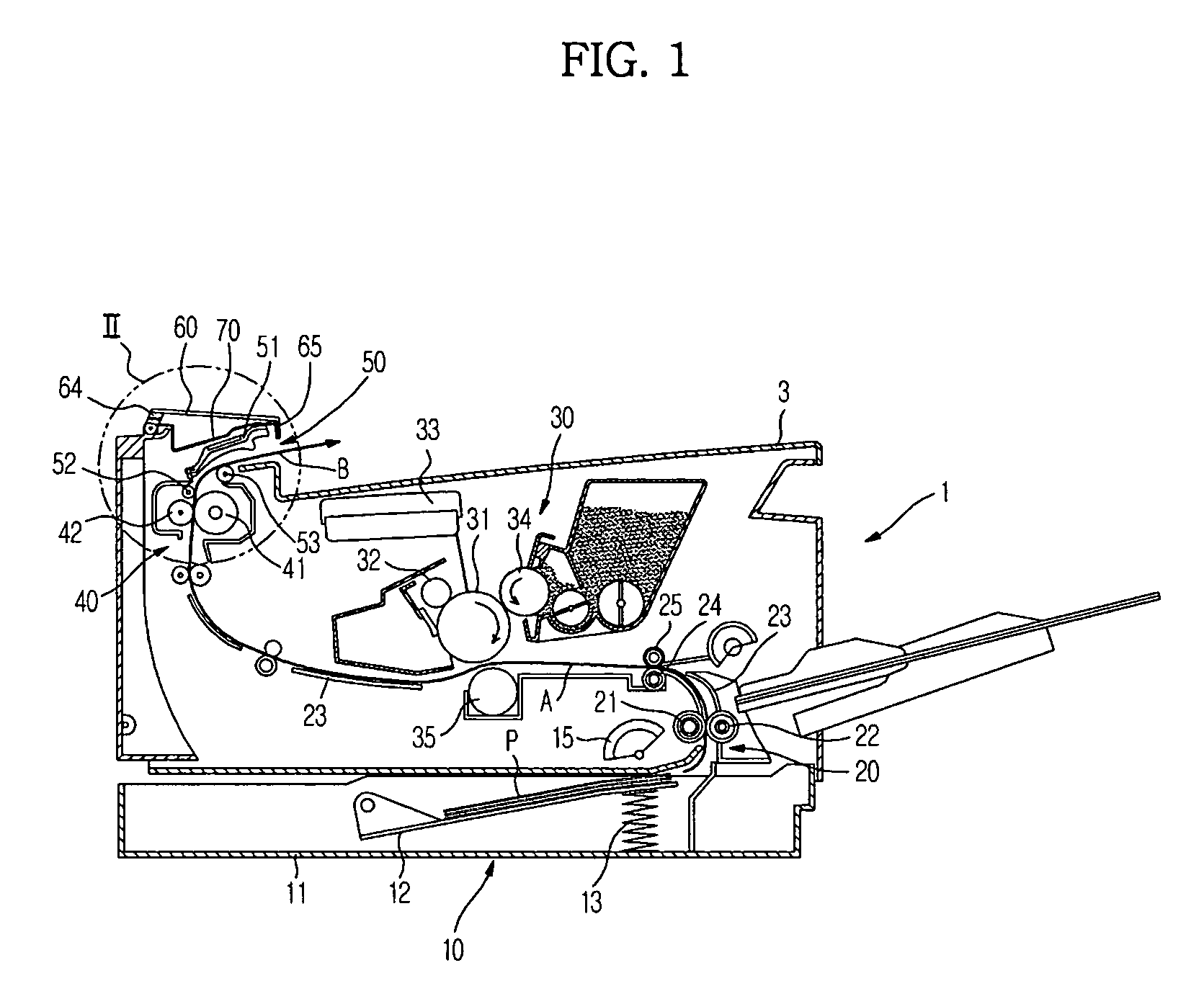
[0030]FIG. 1 shows a schematic constitution of an image forming apparatus in accordance with the present embodiment. An image forming apparatus includes a paper supply unit 10 to load paper P thereon, a feed unit 20 to feed the paper P, an image forming unit 30 to form an image on the paper P, a fusing unit 40 to fuse a transferred image to the paper P, and a paper discharge unit 50 to discharge the paper P.

[0031]The paper supply unit 10 is mounted in a lower portion of a main body 1. The paper supply unit 10 includes a cassette-type paper tray 11, a press plate 12 and a press spring 13, which press the paper P in the paper tray 11 to a pickup roller 15 disposed above the press plate 12. The press spr...


PUM


Abstract

An image forming apparatus capable of minimizing a temperature rise of a cover is disclosed. The image forming apparatus includes a main body, a fusing unit mounted in the main body to fuse an image to paper, a cover mounted to the main body to expose the fusing unit, a heat shielding member mounted proximate to an inner side of the cover to block heat transferred from the fusing unit, an external air circulation chamber formed between the heat shielding member and the cover, in which external air circulates by convection, and at least one external air flow hole, through which the air flows into / out of the external air circulation chamber.

Description

CROSS-REFERENCE TO RELATED APPLICATIONS[0001]This application claims the benefit of Korean Patent Application No. 2007-0056969, filed on Jun. 11, 2007 in the Korean Intellectual Property Office, the disclosure of which is incorporated herein by reference.BACKGROUND[0002]1. Field[0003]The present invention relates to an image forming apparatus, and more particularly to an image forming apparatus which can minimize heat transfer from a fusing unit to an upper cover.[0004]2. Description of the Related Art[0005]An electrophotographic-type image forming apparatus, such as a laser printer, a copying machine, a fax machine, etc., includes an image forming unit which develops an electrostatic latent image on a photosensitive body by using a developer and transfers the image onto paper, and a fusing unit which fuses the transferred image to the paper by using heat and pressure. The paper supplied from a paper supply unit in a main body passes by the image forming unit and the fusing unit in ...

Claims


Application Information

Patent Timeline
Patent Type & Authority Patents(United States)
IPC IPC(8): G03G21/20
CPCG03G15/206G03G21/206G03G2221/1645G03G15/00
Inventor HWANG, GYU DEOKKIM, SUNG HYUOKIM, SUN SOOKIM, JONG WOOBAEK, SUNG KUCHO, HYUN KIRYU, JE HYOUNGKIM, TAE HEE
Owner SAMSUNG ELECTRONICS CO LTD
Why Eureka
Try Eureka