Non uniform electric field chamber for cell fusion

Active Publication Date: 2007-05-10
CELLECTIS SA +1
View PDF6 Cites 0 Cited by
  • Summary
  • Abstract
  • Description
  • Claims
  • Application Information

AI Technical Summary

Benefits of technology

[0088] calculating the third of the first electrode radius of the inner electrode, the second electrode radius of the outer electrode, and the gap between the inner electrode and the outer electrode, such that compression between the biological cells and permeability between cell membranes are maximized and temperature rise is minimized for providing cell fusion in the cell fusion chamber.
[0090] With further consideration of the concept of scalability, with the subject invention, volume of the cell fusion chamber can be increased by simple increasing the electrode height and keeping the ratio r1 / r2 and the gap constant. In addition, by simply increasing the electrode height and keeping r1 / r2 constant, temperature in the medium does not change.

Problems solved by technology

This would result in low cell fusion.
If to compensate, the AC voltage would be increased to maintain a constant compressive force, undesirable heating of the medium would occur which would cause an undesirable temperature rise which would kill the cells.

Method used


Image

  • Non uniform electric field chamber for cell fusion
  • Non uniform electric field chamber for cell fusion
  • Non uniform electric field chamber for cell fusion

Examples


second embodiment

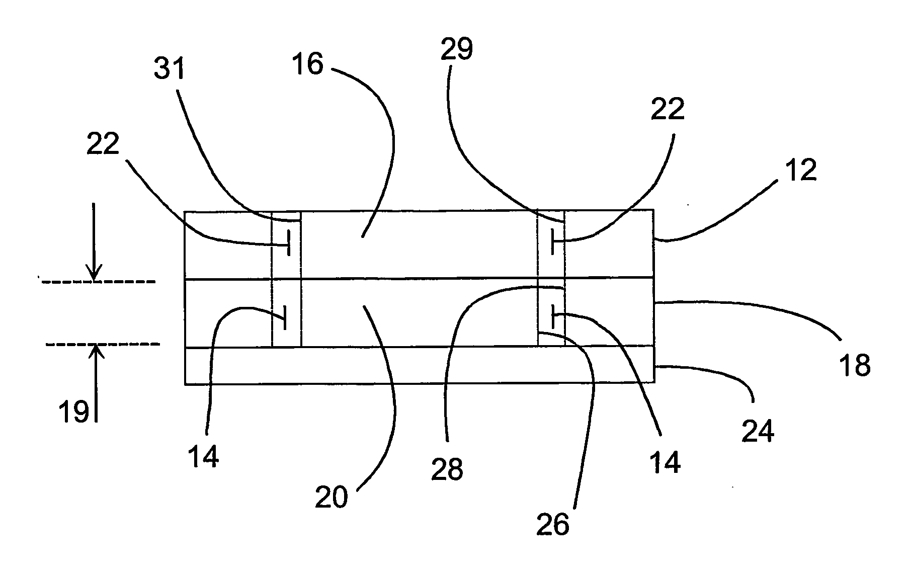
[0148] More specifically, with respect to the invention a non-conductive outer electrode cover member 12 is supported by the outer electrode 18. A non-conductive inner electrode cover member 16 is supported by the inner electrode 20, wherein the outer electrode cover member 12 and the inner electrode cover member 16 define an access channel 22, and wherein the access channel 22 is in communication with the fusion chamber 14.

[0149] Preferably, the non-conductive outer electrode cover member 12 includes a concave outer cover member surface 29 which has an outer cover member radius. Also, preferably, the non-conductive inner electrode cover member 16 includes a convex inner cover member surface 31 which has an inner cover member radius. Preferably, the outer cover member radius is equal to the outer electrode radius, and the inner cover member radius is equal to the inner electrode radius, whereby the access channel 22 is in registration with the fusion chamber 14.

[0150] Non-conductiv...

third embodiment

[0152] a coaxial chamber is illustrated in FIG. 14. Generally, this chamber is a half of a coaxial chamber mounted vertically. When the alignment AC voltage is applied, cell motion will be counter to gravity. This prevents cells from settling to the bottom of the chamber while the waveforms are applied. This chamber may be open or closed with sterile ports and filter relief ports to fill and empty the chamber.

[0153] More specifically, this third embodiment of the apparatus includes a non-conductive support member 40. A conductive outer electrode 43 is supported in a horizontal orientation by the support member 40. The outer electrode 43 includes a conductive concave outer electrode surface 42 which has an outer electrode radius (r2) and has an electrode width. A conductive inner electrode 45 is supported in a horizontal orientation by the support member 40 above the outer electrode 43. The inner electrode 45 includes a conductive convex inner electrode surface 44 which has an inner ...


PUM

PropertyMeasurementUnit
Volumeaaaaaaaaaa
Radiusaaaaaaaaaa
Radiusaaaaaaaaaa

Abstract

An apparatus is provided for carrying out fusion of biological cells (10) and includes a base member (24) on which a conductive outer electrode (18) is supported and has an outer electrode radius (r2) and has an electrode height (19). A conductive inner electrode (20) is supported on the base member (24) and has an inner electrode radius (r1) and also has the electrode height (19). The outer and inner electrodes (18,20) are spaced apart from each other by a gap which defines a fusion chamber (14). The inner electrode radius (r1), the outer electrode radius (r2), and the gap are selected in accordance with a predetermined range of selectable ratios (r1 / r2) in a range from 0.7 to 0.9, wherein a selected gap is limited by the range of selectable ratios (r1 / r2), and wherein a determined ratio (r1 / r2) among the selectable ratios is based on the selected gap, such that compression between the biological cells (10) and permeability between cell membranes are maximized and temperature rise is minimized for providing cell fusion in the fusion chamber (14).

Description

TECHNICAL FIELD [0001] The present invention relates generally to methods and apparatus for fusing biological cells to one another. More specifically, the present invention provides methods and apparatus for treating biological cells with electrical fields, such that the biological cells are aligned and have increased cell membrane contact prior to being subjected to cell fusing electric field pulses. BACKGROUND ART [0002] If a neutrally charged particle, such as a biological cell, is placed in a uniform electric field, such as provided by a pair of same-size planar electrodes, the biological cell does not move toward either one electrode or the other because the attractive forces from both electrodes are the same. [0003] On the other hand, if a neutrally charged biological cell is placed in a non-uniform electric field, such as provided by two electrodes which are both not planar, as shown in PRIOR ART FIG. 1, the biological cell forms a dipole, is attracted to one electrode with g...

Claims


Application Information

Patent Timeline
IPC IPC(8): C12N15/02C12M1/42C12M3/00C12N5/07C12N5/071C12N5/09C12N13/00
CPCC12M35/02C12N13/00
Inventor WALTERS, RICHARD E.
Owner CELLECTIS SA
Why Eureka
Try Eureka