Temperature control system to independently maintain separate molten polymer streams at selected temperatures during fiber extrusion

a temperature control system and temperature control technology, applied in the field of equipment, can solve the problems of not allowing independent control of polymer temperature and negatively affecting the formation of plural component fibers, and achieve the effect of facilitating independent control of temperatur

Active Publication Date: 2007-08-07
HILLS CO
View PDF17 Cites 3 Cited by
  • Summary
  • Abstract
  • Description
  • Claims
  • Application Information

AI Technical Summary

Benefits of technology

[0015]According to the present invention, a temperature control system for use in a fiber extrusion process (e.g., a spunbond process) includes a number of metering pump assemblies including inlets to receive at least two molten polymer streams from a supply source that is connectable to the system. A pump block disposed proximate the metering pump assemblies includes a plurality of flow paths extending within the pump block, where the flow paths are aligned to receive molten polymer flowing from outlets of the metering pump assemblies and to deliver the molten polymer to a spinneret. The flow paths are arranged in flow path sets within the pump block, and each flow path set includes at least one flow path and is spaced a selected distance from the other flow path sets within the pump block so as to facilitate independent control of the temperature of a molten polymer flowing through each flow path set
[0016]Thus, the temperature control system of the present invention permits independent temperature control for two or more molten polymer streams entering the pump block, with the temperatures of the molten polymer streams being further maintained at their respective temperatures prior to and during formation of the extruded fibers. In particular, the molten polymer streams can be substantially maintained at their respective inlet temperatures to the pump block. In scenarios in which two molten polymer streams contain different polymers at significantly different temperatures, the system of the present invention minimizes the temperature rise of the low temperature polymer stream to within about 0-50% of the difference between the incoming temperature of the low temperature polymer stream and the spin beam temperature and / or a maximum temperature for a high temperature polymer stream processed by the system. The amount of temperature differential that can be attained is dependent upon the physical layout necessitated by various design constraints, the flow rates for a given process being run at any given time, the temperatures employed for a given process, and the thermodynamic characteristics of the low temperature polymeric material. For example, in a temperature control system including a spin beam maintained at a temperature of 290° C. and a molten polymer stream with an inlet temperature to the system of 220° C., the exit temperature from the system of the molten polymer stream would be approximately 220° C.-255° C., with variance in exit temperature being based upon flow rate and residence time of the polymer stream within the system.

Problems solved by technology

However, such a system does not allow for independent control of the polymer temperatures.
As previously noted, this can negatively impact the formation of plural component fibers with different polymer components having different degradation temperatures and / or different viscosity characteristics.

Method used


Image

  • Temperature control system to independently maintain separate molten polymer streams at selected temperatures during fiber extrusion
  • Temperature control system to independently maintain separate molten polymer streams at selected temperatures during fiber extrusion
  • Temperature control system to independently maintain separate molten polymer streams at selected temperatures during fiber extrusion

Examples


Embodiment Construction

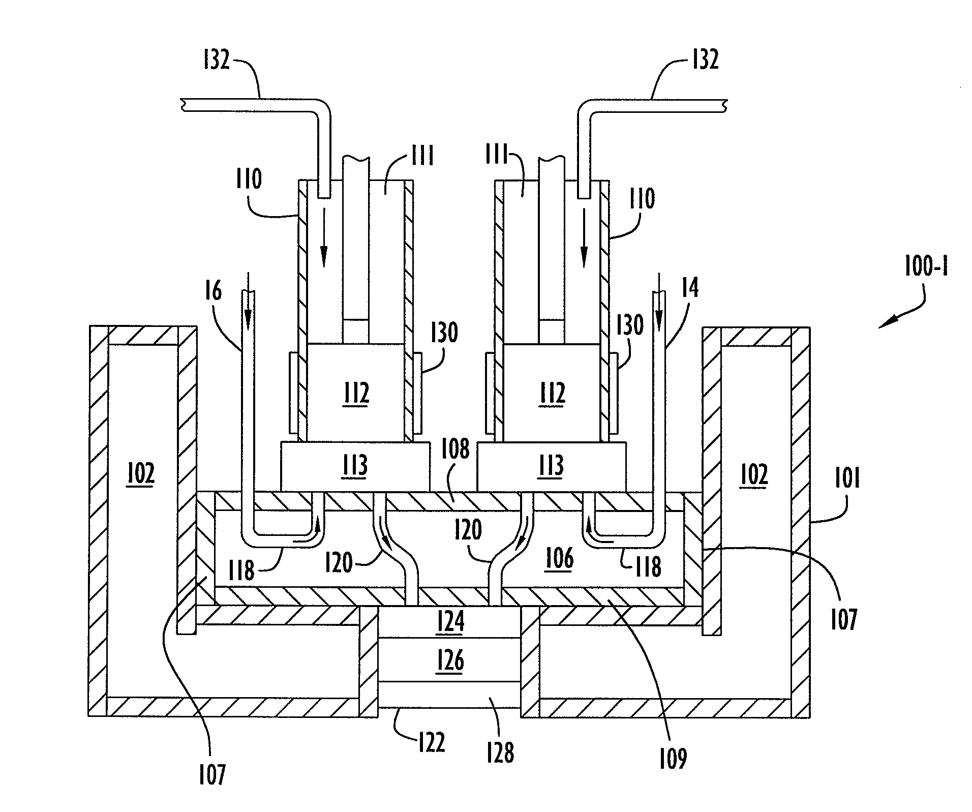
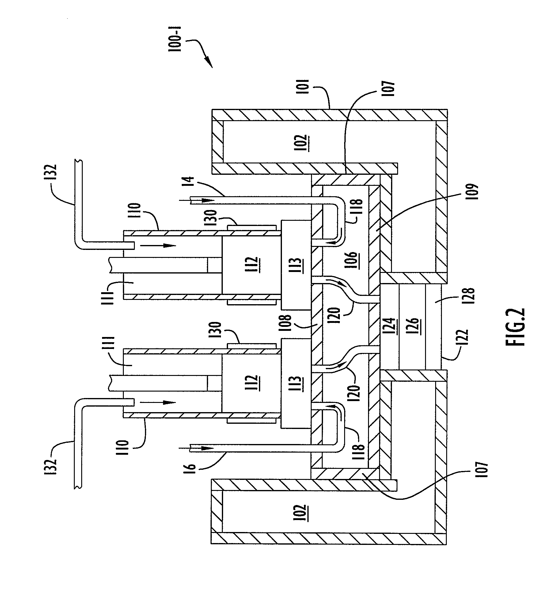
[0024]In accordance with the present invention, a temperature control system for a fiber extrusion system is provided for processing two or more molten polymer streams so as to substantially and independently maintain each molten polymer stream at a selected temperature prior to and during formation of extruded polymer fibers. The temperature control system may be utilized in any fiber extrusion process including, without limitation, spunbond and meltblown systems. In addition, the temperature control system may be utilized in combination with a fiber extrusion process to form any type of mono and / or plural component fibers with any selected cross-sectional geometries including, without limitation, side-by-side, sheath / core, islands-in-the-sea, segmented pie, ribbon-shaped, multi-lobed, etc.

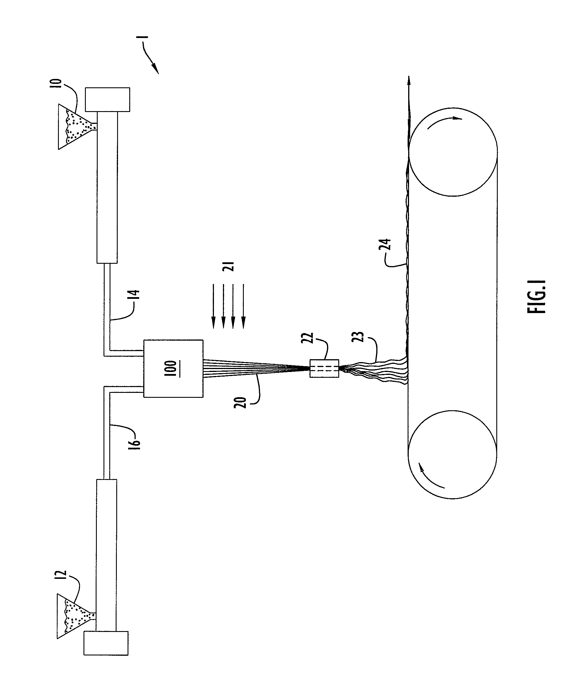
[0025]An exemplary fiber extrusion process is illustrated in FIG. 1, in which the temperature control system of the present invention is combined with a spunbond system. Spunbond system 1 include...


PUM

PropertyMeasurementUnit
exit temperatureaaaaaaaaaa
temperatureaaaaaaaaaa

Abstract

A temperature control system for use in a fiber extrusion process includes a number of metering pump assemblies including inlets to receive at least two molten polymer streams from a supply source that is connectable to the system. A pump block disposed proximate the metering pump assemblies includes a plurality of flow paths extending within the pump block, where the flow paths are aligned to receive molten polymer flowing from outlets of the metering pump assemblies and to deliver the molten polymer to a spinneret. The flow paths are arranged in flow path sets within the pump block, and each flow path set includes at least one flow path and is spaced a selected distance from the other flow path sets within the pump block so as to facilitate independent control of the temperature of a molten polymer flowing through each flow path set.

Description

CROSS REFERENCE TO RELATED APPLICATIONS[0001]This application claims priority from U.S. Provisional Patent Application Ser. No. 60 / 415,093, entitled “Pump Block For Multi-Component Spin Beam To Maintain Separate Polymer Temperatures”, filed Oct. 2, 2002. The disclosure of this provisional patent application is incorporated herein by reference in its entirety.BACKGROUND OF THE INVENTION[0002]1. Field of the Invention[0003]The present invention relates to equipment and corresponding methods for producing extruded fibers. In particular, the present invention relates to heat control equipment and corresponding methods to control the temperature of molten polymer being extruded to form synthetic fibers.[0004]2. Description of the Related Art[0005]Plural component fiber extrusion processes (e.g., conjugate filament, conjugate staple, conjugate spunbond, and conjugate monofilament) typically employ two or more polymers in combinations and fiber cross-section structure in the production of ...

Claims


Application Information

Patent Timeline
Patent Type & Authority Patents(United States)
IPC IPC(8): D01D1/06D01D4/02
CPCD01D1/09D01D4/06
Inventor JOHNSTON, BRIANHAGGARD, JEFFWILKIE, ARNOLDCHERN, RUEYMILLER, MARKOWEN, TONYQUINLIVAN, JOHNMIRE, TEDSOUCIER, BRENTMOSCHETTI, KEVIN
Owner HILLS CO
Why Eureka
Try Eureka