On-demand inkjet printer and drive method and drive circuit for same

Inactive Publication Date: 2005-08-23
FUJIFILM HLDG CORP
View PDF17 Cites 8 Cited by
  • Summary
  • Abstract
  • Description
  • Claims
  • Application Information

AI Technical Summary

Benefits of technology

[0023]Thereby, even if the amount of ink is controlled, since tonal representation can be achieved by means of both the amount of ink and the number of dots, it does not matter if the dynamic range of the amount of ink is narrow, compared to a conventional dot toning head. For example,

Problems solved by technology

However, in an inkjet printer, it is not easy to control the dot position or dot size at each nozzle.
For the above reasons, it is difficult to perform control whereby the jet timing of a certain nozzle is shifted independently, and consequently, control of individual dot positions is difficult.
In the case of a system for controlling the timing by providing independent drive sources for each nozzle, although such control is technically possible, given the fact that nozzles are currently increasing in number, this cannot be seen as a practicable system, from the viewpoints of circuit size or cost.
Furthermore, in an inkjet head using thermal elements, in order to reduce costs, time division matrix driving is implemented whereby the total group of nozzles are divided into a plurality of blocks, and each plurality of nozzles is driven simultaneously, and this means that it is just as difficult to shift the timing for one particula

Method used


Image

  • On-demand inkjet printer and drive method and drive circuit for same
  • On-demand inkjet printer and drive method and drive circuit for same
  • On-demand inkjet printer and drive method and drive circuit for same

Examples


first embodiment

[0052][First Embodiment ]

[0053]FIG. 6 is a circuit diagram of an inkjet printer according to a first embodiment of the present invention; FIG. 7 is a compositional diagram of a drive waveform generator unit; FIG. 8 is a compositional diagram of a head drive unit; and FIG. 9 is a timing chart of the composition in FIG. 6.

[0054]As shown in FIG. 6, the printer control circuit is constituted by a control unit 4, head unit 20, and mechanism 2 (see FIG. 2). The control unit 4 comprises an interface 40, CPU 41, memory 43, controller 42, image memory 44, mechanism driver 45, drive waveform generator unit 46, and the like.

[0055]The interface 40 serves to exchange commands and data with the host 5. The CPU 41 performs main control of the printer 1, using the memory 43. The image memory 44 stores image data that is to be printed. This image data consists of data for each pixels. The controller 42 generates drive signals of various types, according to instructions from the CPU 41, as described ...

second embodiment

[0071][Second Embodiment]

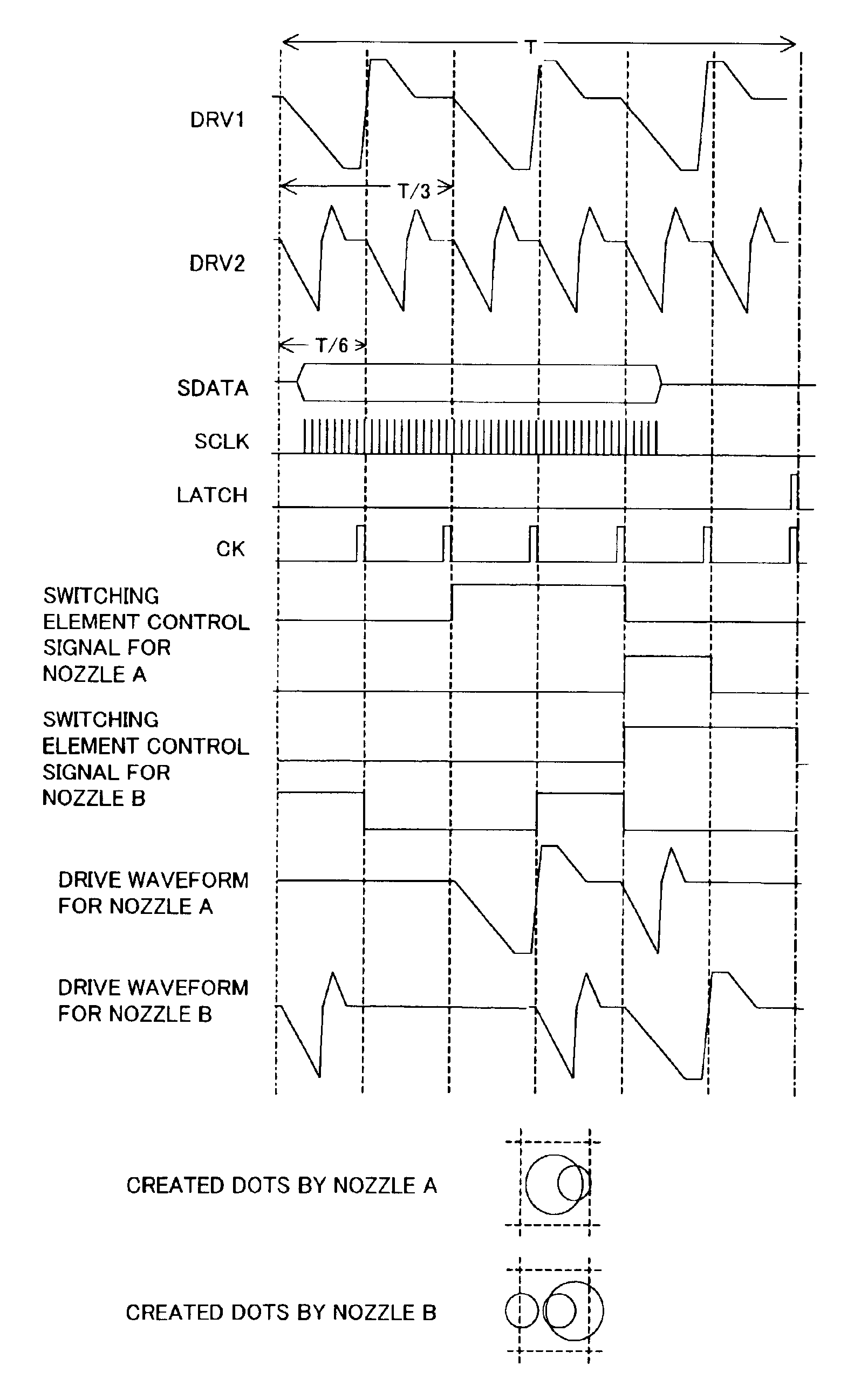
[0072]FIG. 13 is a circuit diagram of an inkjet printer according to a second embodiment of the present invention; FIG. 14 is a compositional diagram of a head drive unit in FIG. 13; FIG. 15 is a compositional diagram of a subsidiary shift register; FIG. 16 is an explanatory diagram of a decoder; and FIG. 17 is a timing chart of the composition in FIG. 13.

[0073]In FIG. 13 and FIG. 14, elements which are the same as those in FIG. 6, FIG. 7 and FIG. 8 are similarly labelled. As shown in FIG. 13, the difference with respect to the first embodiment is that a plurality of drive waveform generator units 46-146-2 (in this case, two drive waveform generator units) are provided, in such a manner that a plurality of ink particles are generated by a plurality of head drive waveforms (DRV1, DRV2).

[0074]More specifically, as illustrated in FIG. 17, the first drive waveform generator unit 46-1 generates a first drive signal DRV1 for producing a relatively large ink partic...


PUM


Abstract

In an inkjet head, both tones and smoothing can be represented suitably through use of a small number of drive waveforms. A drive waveform generator unit (46) generates drive waveforms for emitting a ink particle to form dots of a same size within one cycle that is an integral fraction of the cycle for one pixel, a print data generator unit (42) generates print data of a plurality of bits for selecting said drive waveform in said cycle for one pixel, and a head drive unit (47) drives the nozzles of said head by selecting said drive waveform in accordance with said print data. Thereby, tones and smoothing can be represented suitably, through use of a small number of different waveforms.

Description

[0001]This application is a continuation of international application PCT / JP00 / 02140, filed on Mar. 31, 2000.TECHNICAL FIELD[0002]The present invention relates to an on-demand inkjet printer for jetting ink according to demand, and a drive method and drive circuit for same, and more particularly, to an on-demand inkjet printer, drive method and drive circuit for same capable of tonal representation for each pixels and edge smoothing.BACKGROUND ART[0003]Inkjet printers are widely used as low-cost printers. In an inkjet printer of this kind, rather than simply printing characters, it is necessary to print images. Therefore, tonal representation for each pixels and edge smoothing is required.[0004]On the other hand, in laser printers, this can be achieved readily by varying the size of the dots, and altering the dot positions by pulse width modulation of the laser. However, in an inkjet printer, it is not easy to control the dot position or dot size at each nozzle. One of the reasons f...

Claims


Application Information

Patent Timeline
IPC IPC(8): B41J2/045
CPCB41J2/0458B41J2/04581B41J2/04588B41J2/04595
Inventor NOU, HIROSHI
Owner FUJIFILM HLDG CORP
Why Eureka
Try Eureka