Method for forming foam products and system thereof

A product and foaming agent technology, applied in the field of forming foamed products, can solve the problems of large barrel pressure, increased feeding screw resistance, and thinning of foamed products, etc., to achieve small barrel pressure and feeding screw resistance small effect

Inactive Publication Date: 2011-09-07
UNION PLASTIC HANGZHOU MACHINERY
View PDF4 Cites 7 Cited by
  • Summary
  • Abstract
  • Description
  • Claims
  • Application Information

AI Technical Summary

Problems solved by technology

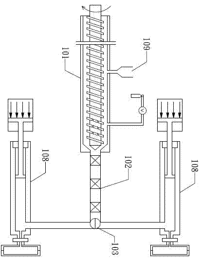
[0016] This method has the following disadvantages: 1. When there is a high-concentration foaming agent in the feed liquid, in order to obtain a single-phase, non-nuclear, uniform feed liquid that enters the discharge cylinder 108 from the feed cylinder 101, it is necessary to provide a high The back pressure of the critical pressure of the foaming agent; thus, the injection pressure of the foaming agent into the feeding cylinder increases, the difficulty of injection increases, and the cost increases
[0017] 2. In order to provide a sufficiently high continuous pressure in the discharge cylinder to maintain the dissolution of the high-concentration foaming agent in the discharge cylinder, which is conducive to increasing the number of nucleation in the air chamber, a high pressure is required in the discharge cylinder to The feed liquid is injected into the discharge cylinder, thus increasing the resistance of the feed screw, resulting in a large pressure on the barrel and high cost
However, when the area of ​​the opening cross-section of the steel mold gap is reduced, the produced foamed products will become thinner, and thick foamed products cannot be produced; on the contrary, in order to manufacture thick foamed products, the steel mold gap should be increased The area of ​​the opening cross-section will reduce the pressure drop rate during the nucleation of the feed liquid, so that the desired microcellular foamed product cannot be obtained

Method used

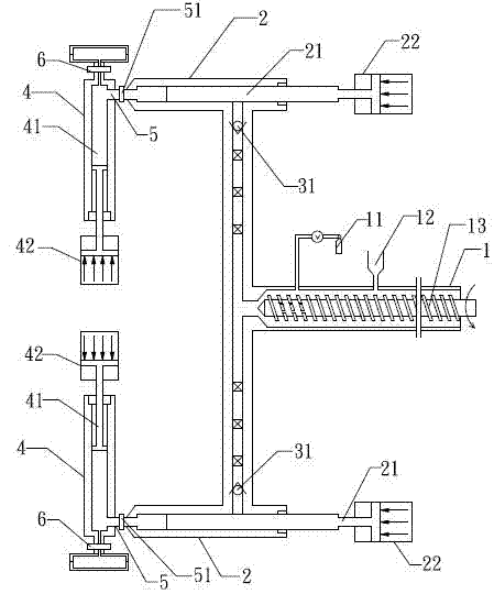
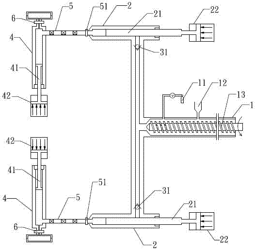

Image

  • Method for forming foam products and system thereof
  • Method for forming foam products and system thereof
  • Method for forming foam products and system thereof

Examples


Embodiment Construction

[0073] With reference to accompanying drawing, further illustrate the present invention:

[0074] The blowing agent of the present invention may contain a chemical blowing agent or a nucleating agent, but it is better to use a purely physical blowing agent. When chemical blowing agents are used, unreacted chemical blowing agents or chemical reaction by-products of chemical blowing agents are often left on the product; the use of chemical blowing agents is not conducive to the recycling and reuse of products, and the general chemical The cost of blowing agent is also higher.

[0075] The invention can manufacture polymer foam products with air chambers. However, when the present invention is used to manufacture microcellular foamed products, and the desired cell density is very high, the nucleation contribution of the nucleating agent is meaningless, so the nucleating agent is seldom used.

[0076] The physical blowing agent that the present invention uses is a kind of gas un...


PUM


Abstract

The invention discloses a method for injecting single-phase solution in a mold to form foam products, which comprises the steps of foaming agent introducing, buffering in feed liquid conveying and single-phase solution obtaining. The method for forming foam products comprises the steps of: in a polymer processing system, conveying polymer material to a mold cavity with an inlet from the upper stream of a polymer processing space through a selectable path, wherein the inlet of the mold cavity is connected with a tail end outlet in lower stream direction; introducting the foaming agent that is gaseous in environment condition into the polymer material; and forming the foam products with the polymer material. The system for forming foam products consists of a processing device with a screw rod, at least two material storage cylinders, at least one discharge cylinder, and at least one mold cavity with an inlet, wherein the inlet of the mold cavity is connected with the corresponding tail end outlet of the discharge cylinder. The invention has the advantages of being capable of keeping the single-phase solution at high pressure continuously and not influencing the introducing of the foaming agent; in addition, resistance of a feeding screw rod is small and for the bearing pressure of the cylinder is small.

Description

technical field [0001] The present invention relates to a method and system for forming foamed products. technical background [0002] One of a chemical blowing agent or a physical blowing agent is mixed with a molten polymer precursor to produce a foamed product of the polymer. For example, a chemical blowing agent, typically a low molecular weight organic compound, is mixed with molten polymer and heated to a critical temperature to release at least one gas to produce a polymer foamed product. Physical blowing agents, which are essentially gases in the atmosphere, are introduced into the molten polymer during processing or become an ingredient contained in the polymer under pressure to produce foamed polymer products. Polymer foamed products produced by early foaming technology often have relatively large voids or air cells, that is, the air cell size is greater than 100 microns, and there is a non-uniform air cell size distribution in the foamed product. Air cell densit...

Claims


Application Information

Patent Timeline
Patent Type & Authority Applications(China)
IPC IPC(8): B29C67/20
Inventor 陆纬庭
Owner UNION PLASTIC HANGZHOU MACHINERY
Why Eureka
Try Eureka