Recording/reproducing separated type head with heat radiating structure

a technology of heat radiating structure and separated type head, which is applied in the field of recording/reproducing separated type head and inductive magnetic thin film head, can solve the problems of signal disappearance, deformation of head posing an increasingly serious problem, and complicated manufacturing process, so as to minimize the temperature rise of the head itself, the effect of reducing the temperature rise of the head and reducing the production cos

Inactive Publication Date: 2005-08-30
HITACHI GLOBAL STORAGE TECH JAPAN LTD
View PDF2 Cites 2 Cited by
  • Summary
  • Abstract
  • Description
  • Claims
  • Application Information

AI Technical Summary

Benefits of technology

[0025]In order to supply such a head whose deformation is restrained and which is highly reliable even at a low flying height, it is essential to minimize the temperature rise of the head itself. According to the present invention, the rise of the head's own temperature is restrained by improving the heat radiating structure, and it is thereby made possible to supply a head less susceptible to deformation.

Problems solved by technology

However, there is also a disadvantage of complicating the manufacturing process.
However, along with the lowering of the flying height, the deformation of heads is posing an increasingly serious problem, because the deformation of heads would invite localized narrowing of the gap between the heads and the recording medium, and there would be a case that the heads and the recording medium would collide, which would in the worst case result in signal disappearance due to damaging of the recording medium or sliding of the heads.
At the same time, it is also effective to facilitate heat radiation and thereby make it difficult for the heads to generate heat.
Therefore, an essential challenge is how to effectively radiate heat due to, for instance, the Joule heating of the coil 12 and the hysteresis heating of the upper pole 14 and the lower pole 10.
Thus the point is how to cause the substrate to radiate the heat generated by the inductive magnetic thin film head, and therefore how to bring the source of heat generation and the substrate close to each other poses an essential challenge.
Unless these gaps are filled with A12O3 (alumina), the magnetic properties of the magnetic thin films formed over them, such as the lower shield 3 and the GMR film 5, will become deteriorated, eventually with an adverse consequence on the electric properties and life of the head.

Method used


Image

  • Recording/reproducing separated type head with heat radiating structure
  • Recording/reproducing separated type head with heat radiating structure
  • Recording/reproducing separated type head with heat radiating structure

Examples


embodiment 1

[Embodiment 1]

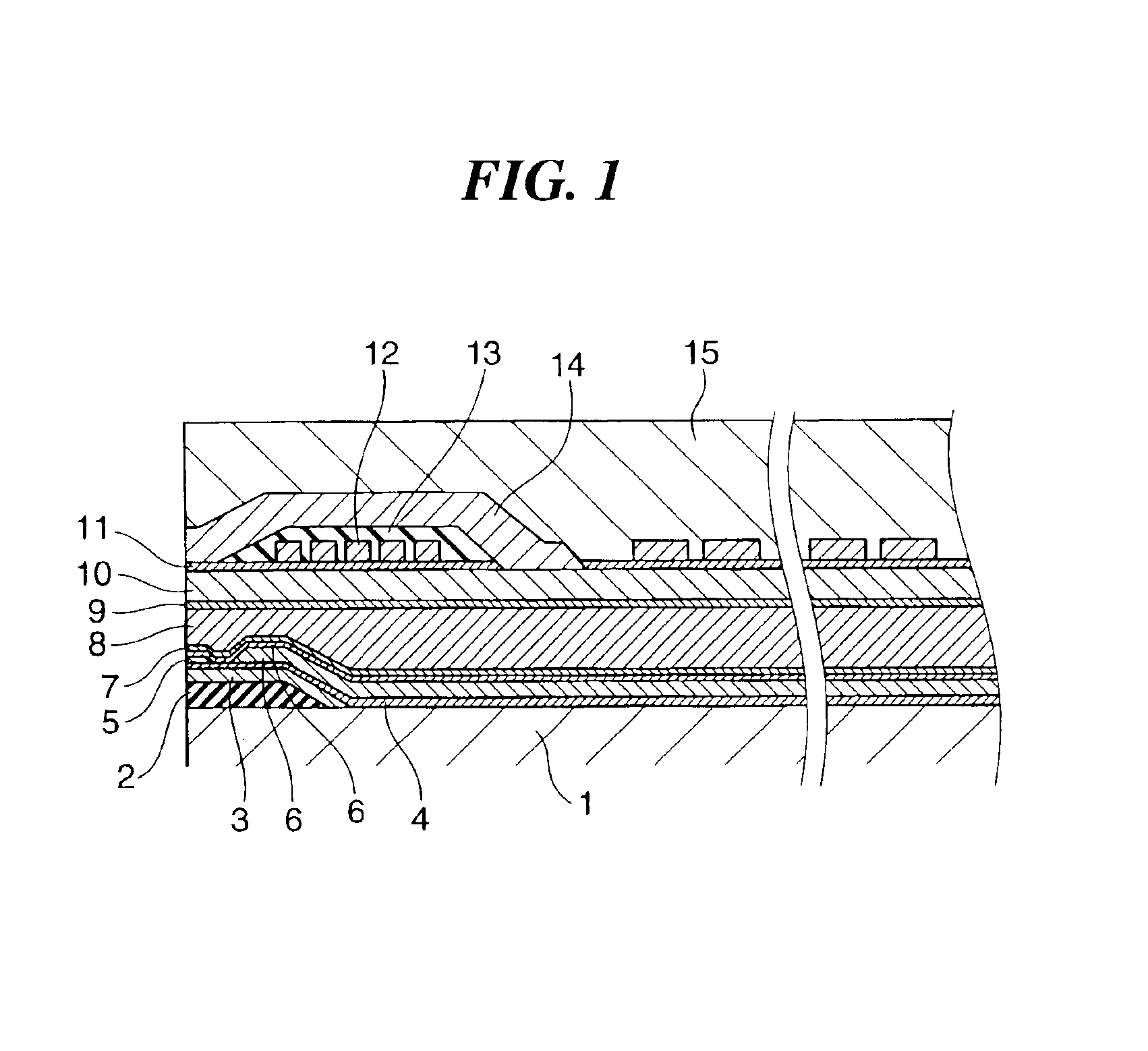
[0034]FIG. 1 is a sectional view showing in detail the configuration of an upper shield / lower pole separated version of recording / reproducing separated type head, which is Embodiment 1 of the present invention. In the recording / reproducing separated type head according to the prior art shown in FIG. 4 and FIG. 5, the insulating film 2 is formed all over the substrate 1. In this embodiment, the area in which the insulating film 2 is formed is limited to the vicinity of the GMR film 5. It is the same as what is shown in FIG. 5 in all other respects of the configuration. This configuration enables the heat of Joule heating by the coil 12 to be guided to the substrate 1 without being obstructed by the insulating film 2. The electrodes 6, the upper shield film 8, the lower shield 3 and the lower pole 10 that are formed in-between are metallic thin films of high thermal conductivity, and little affects the escape of heat generated in the coil 12 to the substrate 1. Similarly...

embodiment 2

[Embodiment 2]

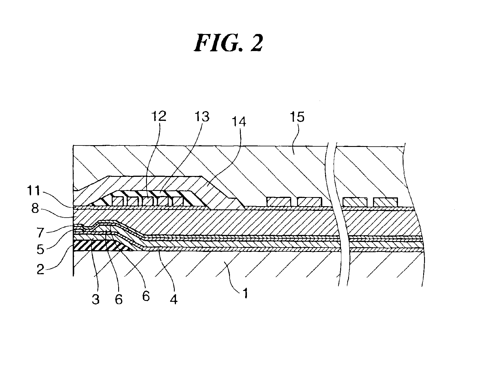
[0056]Unlike Embodiment 1 described above, which is an upper shield / lower pole separated type head, this embodiment is an upper shield / lower pole merged version of recording / reproducing separated type head as shown in FIG. 2. The upper shield / lower pole merged type head requires more strict control of the manufacturing process than the upper shield / lower pole separated type head described above because its GMR head is more susceptible to the influence of the recording magnetic field. However, as its structure is simpler, the burden on the manufacturing process is smaller, which means a cost advantage as well.

[0057]The recording / reproducing separated type head embodying the invention in this mode permits dispensation with steps (10) and (11) in the process for Embodiment 1 described above. The process for this embodiment is the same as that for Embodiment 1 described above in all other respects.

[0058]In the head embodying the invention in this mode, the upper shield fil...

embodiment 3

[Embodiment 3]

[0059]Embodiment 1 and Embodiment 2 described above have structures in which most of the insulating film 2 over the substrate 1 is removed. However, the GMR head is supplied with sense currents from the electrodes 6. For this reason, if the electrodes 6 are electrically connected to the substrate 1, the sense currents will be shunted, resulting in a drop in electrical output.

[0060]To solve this problem, it is effective to thicken the insulating film 2 between the electrodes 6 and the substrate 1. Needless to mention, this is done without sacrificing the high level of heat radiation, which is an object of the present invention.

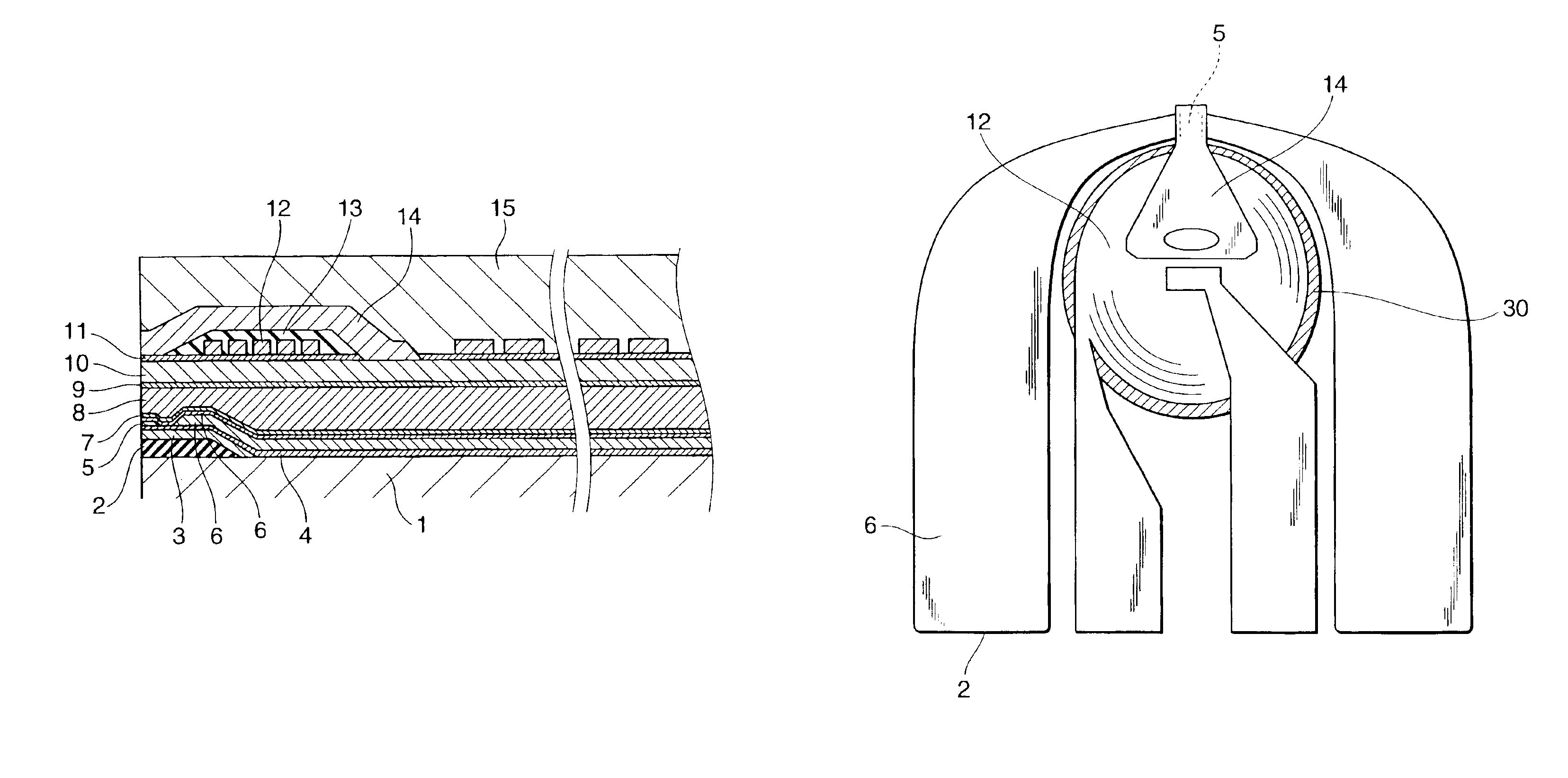
[0061]FIG. 8 schematically illustrates this embodiment, wherein the head is viewed from the upper pole 14 side.

[0062]The electrodes 6 are given such a size and positions that they may not cross the coil 12. The insulating film 2 is removed only underneath the coil 12 or in the area slightly larger than the coil 12 (insulating film-removed area 30)...


PUM

PropertyMeasurementUnit
thicknessaaaaaaaaaa
temperatureaaaaaaaaaa
thicknessaaaaaaaaaa

Abstract

An area in which an insulating film is formed over a substrate of a recording/reproducing separated type head is limited to the vicinity of a GMR film. This enables heat of Joule heating by a coil to be guided to the substrate without being obstructed by the insulating film. Electrodes, an upper shield film, a lower shield and a lower pole that are formed in-between are metallic thin films of high thermal conductivity, and accordingly have little influence. Similarly, gap films and a separation film that are positioned in-between, though they are electrically insulating films made of A12O3, have no great influence because of their thinness. According to the invention, a rise of the head's own temperature is restrained by efficiently radiating heat generated by the head itself to the substrate. As a result, it is thereby made possible to provide a highly reliable recording/reproducing separated type head whose deformation quantity is smaller and which can avoid coming into contact with a recording medium.

Description

BACKGROUND OF THE INVENTION[0001]1. Field of the Invention[0002]The present invention relates to a recording / reproducing separated type head and an inductive magnetic thin film head for use in magnetic disk apparatuses.[0003]2. Description of the Prior Art[0004]Along with the capacity enlargement of magnetic disk apparatuses, the requirement for higher recording densities is increasing year after year. The apparatuses are required to be smaller and slower in circumferential speed. To meet these requirements, state-of-the-art magnetic disk apparatuses use a giant magnetoresistive (GMR) film, and their recording track width has been reduced less than 0.4 μm and their gap between the head and the recording medium (hereinafter referred to as the flying height), to 15 nm, both approximately.[0005]FIG. 3 shows a perspective view of a recording / reproducing separated type head using a GMR head. The recording / reproducing separated type head has a structure in which an inductive magnetic thin...

Claims


Application Information

Patent Timeline
Patent Type & Authority Patents(United States)
IPC IPC(8): G11B5/39G11B5/31
CPCB82Y10/00B82Y25/00G11B5/3136G11B5/3967G11B5/313G11B5/3903G11B2005/3996
Inventor YUITO, ISAMUAKAMATSU, KIYOSHI
Owner HITACHI GLOBAL STORAGE TECH JAPAN LTD
Why Eureka
Try Eureka