Threaded hoist ring screw retainer

a technology of hoist ring and screw retainer, which is applied in the direction of hoisting equipment, couplings, transportation and packaging, etc., can solve the problems of snap rings being separated from the hoist ring assemblies, failing or being improperly installed, and adding to the complexity of the assembly

Inactive Publication Date: 2012-06-19
MJT HLDG
View PDF9 Cites 217 Cited by
  • Summary
  • Abstract
  • Description
  • Claims
  • Application Information

AI Technical Summary

Problems solved by technology

If an element is not present in the design, it cannot fail or be improperly installed.
This adds to the complexity of the assembly.
Also, there has been some concern that during handling, installation, or use, the snap rings might become separated from the hoist ring assemblies.
This might prevent the hoist ring from being properly tightened to a load.

Method used


Image

  • Threaded hoist ring screw retainer
  • Threaded hoist ring screw retainer
  • Threaded hoist ring screw retainer

Examples


Embodiment Construction

[0021]The following description of preferred embodiments generally relates to omni-positional hoist ring assembles.

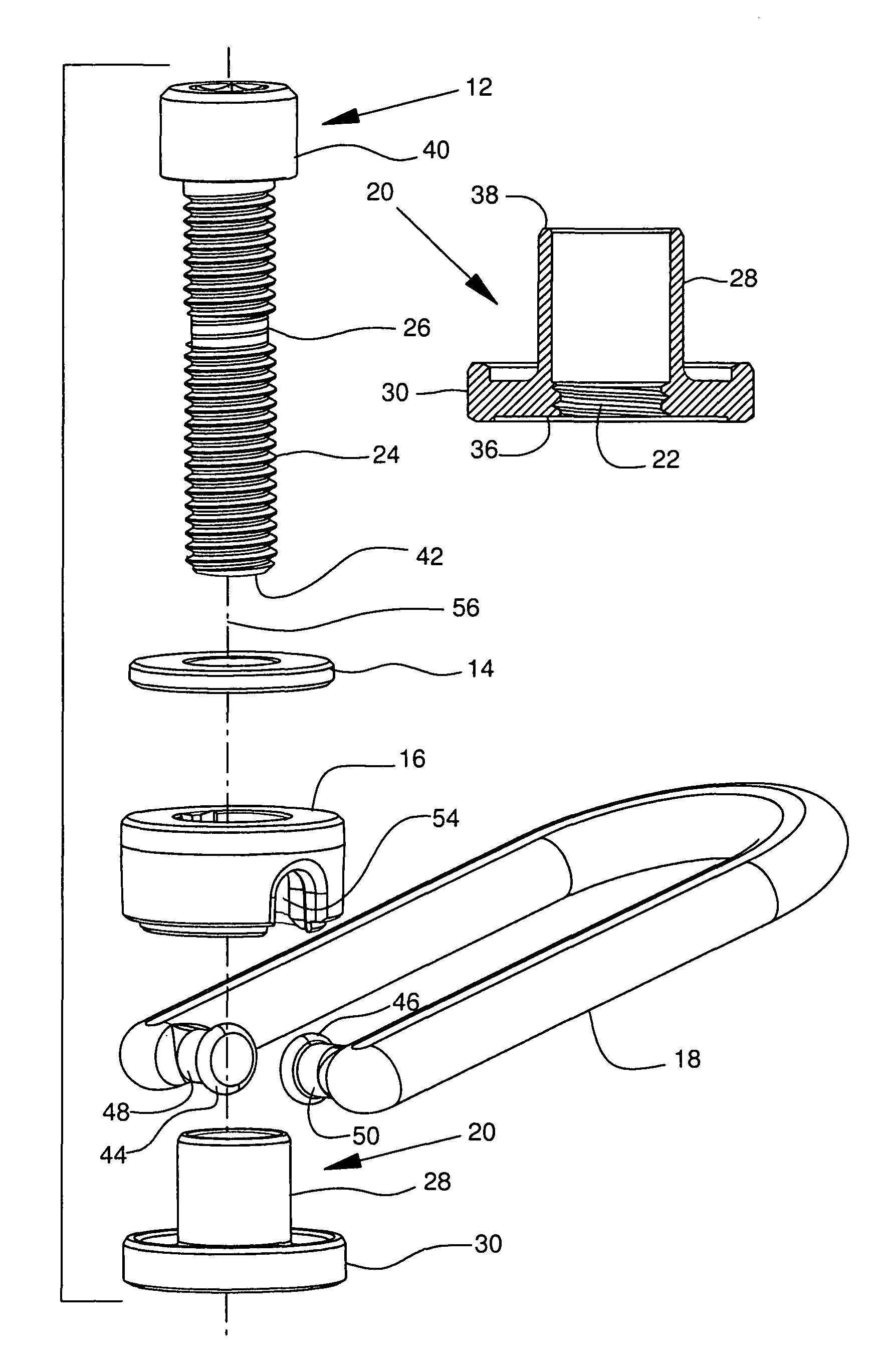
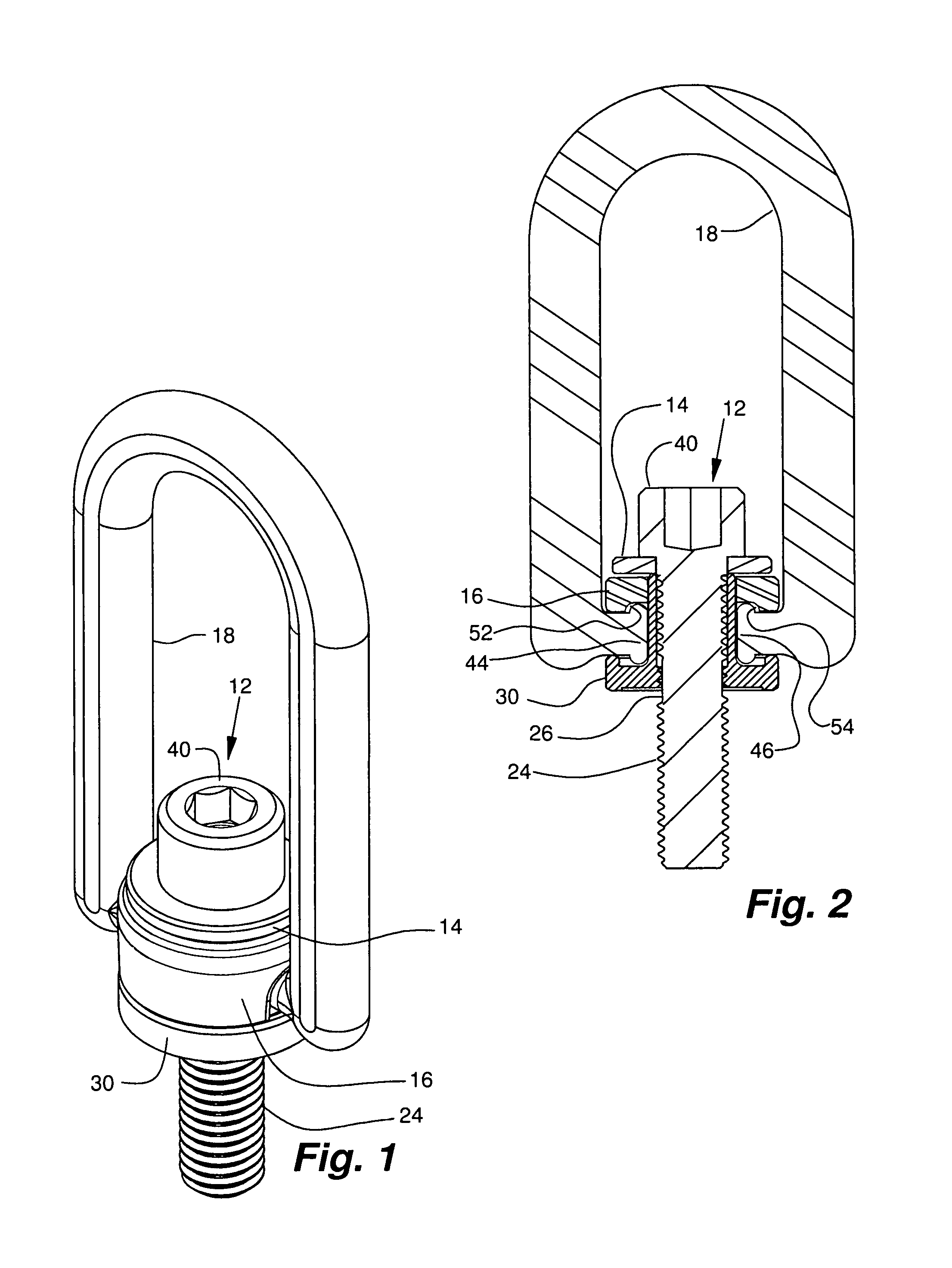
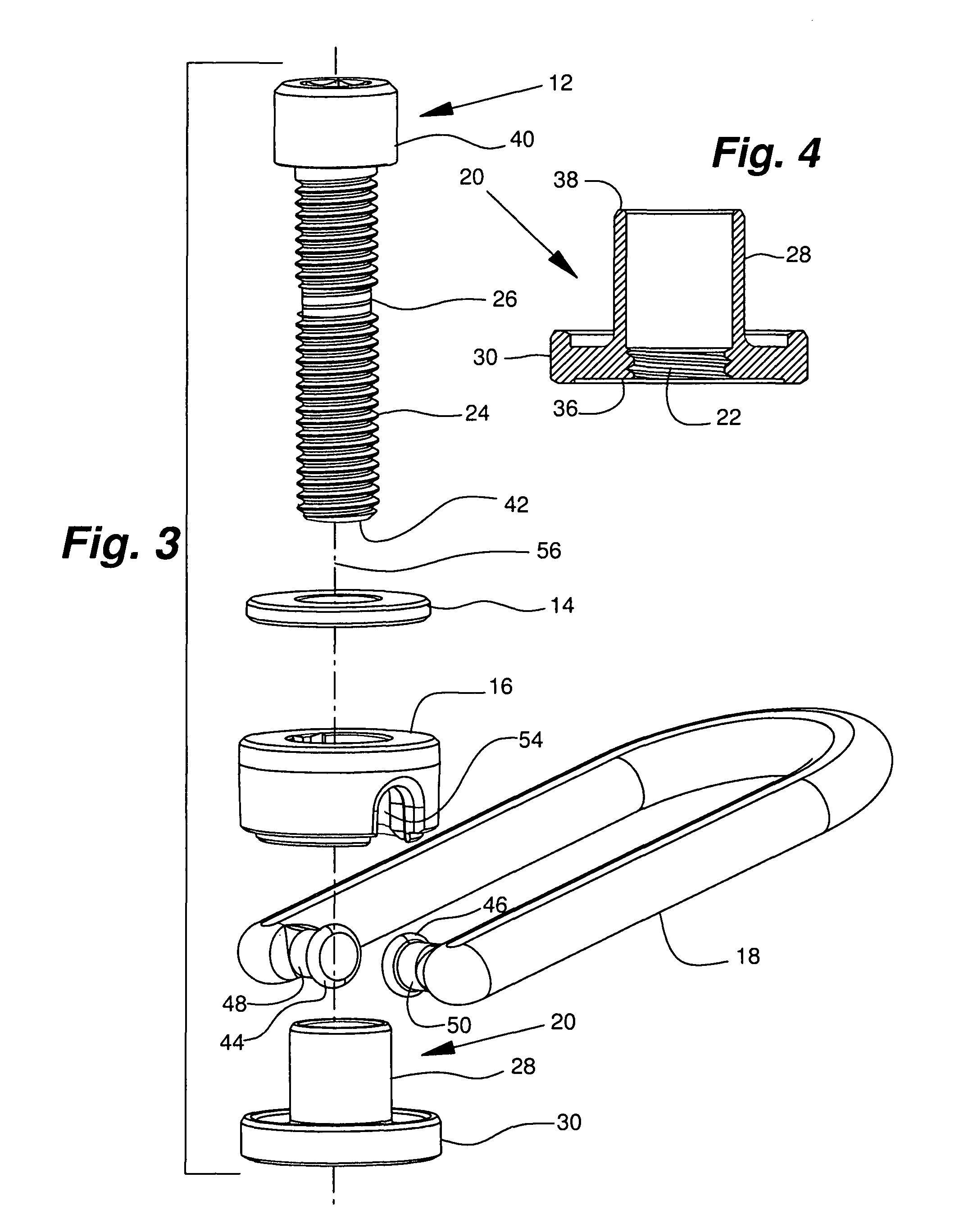
[0022]Referring particularly to the accompanying drawings, in the embodiment chosen for illustration, a hoist ring assembly includes a lifting loop element 18 that is captured for pivotal movement within a body element 16. Body element 16 is rotatably captured between a thrust washer element 14 and a bushing element that is indicated generally at 20. Thrust washer element 14 and bushing element 20 are adapted to be mounted to a load 32 by a mounting screw element that is indicated generally at 12, and which extends axially through them and into load 32.

[0023]In the embodiment chosen for purposes of illustration, bushing element 20 includes a sleeve 28 and a flange 30. Sleeve 28 is a generally right cylinder having proximal end 36 and distal end 38 axially opposed to one another. Sleeve 28 includes an internal thread 22 extending for at least a portion of the internal ax...


PUM


Abstract

An omni-positional hoist ring assembly including a bushing element that includes a sleeve with an axial length, a proximal end and a distal end. A load bearing flange is radially disposed about the proximal end of the sleeve. The sleeve has an internal thread extending at least part way of the axial length of the sleeve. A mounting screw element has a major axis, a head, and a shank disposed generally co-axially around the major axis. The shank includes a threaded shank portion and a bearing portion. The bearing portion is a generally cylindrical axially extending portion of the shank that has a diameter approximately equal to the minor diameter of the thread in the threaded shank portion. A thrust washer element is provided between the head and the distal end of the sleeve. A body element receives the in-turned opposed ends of the legs of a lifting loop element in sockets. The lifting loop is free to pivot. The body element is free to rotate about the sleeve, so the lifting loop will self align with a load that is applied to it from any direction within a hemisphere centered on the major axis of the mounting screw element. The elements of the hoist rig assembly are assembled by aligning them and inserting the mounting screw element into the sleeve and threadably advancing it until the bearing is aligned with the internal thread so further rotation of the mounting screw element does not threadably advance the mounting screw element relative to the sleeve.

Description

RELATED APPLICATIONS[0001]This application claims the benefit of U.S. Provisional Application No. 61 / 152,935, filed Feb. 16, 2009.TECHNICAL FIELD OF THE INVENTION[0002]The present invention relates generally to omni-positional hoist rings and particularly to hoist ring assemblies that are held in an assembled configuration.BACKGROUND OF THE INVENTION[0003]Previous hoist ring mounting screws had been held in an assembled configuration with a thrust washer element, a bushing element, a rotatable body element, and a pivotally mounted lifting loop element by way of a snap ring or a retaining ring on the hoist ring mounting screw. The use of a snap ring in an annular groove on the shank of a mounting screw is disclosed, for example, in Tsui U.S. Pat. No. 5,405,210, and in Tsui et al. U.S. Pat. No. 4,641,986, both of which are hereby incorporated herein by reference as though fully set forth hereat. The use of a retention ring is disclosed, for example, in Chandler U.S. Pat. No. 5,352,056...

Claims


Application Information

Patent Timeline
Patent Type & Authority Patents(United States)
IPC IPC(8): B66F19/00
CPCB66C1/66F16G15/08Y10T403/32213Y10T403/32975Y10T403/32221
Inventor THOMECZEK, JOHN
Owner MJT HLDG
Why Eureka
Try Eureka